Toyota Tacoma (2015-2018) Service Manual: Pump Motor Relay (C1253)
DESCRIPTION
The motor relay (semiconductor relay) is built into the master cylinder solenoid and drives the pump motor based on a signal from the skid control ECU (master cylinder solenoid).
|
DTC No. |
DTC Detecting Condition |
Trouble Areas |
|---|---|---|
|
C1253 |
Open in motor system circuit (motor input circuit) |
|
WIRING DIAGRAM
.png)
CAUTION / NOTICE / HINT
NOTICE:
- When replacing the skid control ECU (master cylinder solenoid), perform
zero point calibration (See page
.gif) ).
). - Inspect the fuses for circuits related to this system before performing the following inspection procedure.
HINT:
Start the inspection from step 1 when using Techstream and start from step 3 when not using Techstream.
PROCEDURE
|
1. |
PERFORM ACTIVE TEST USING TECHSTREAM (MOTOR RELAY) |
(a) Connect Techstream to the DLC3.
(b) Turn the ignition switch to the ON position.
(c) Turn Techstream ON.
(d) Select the Active Test mode on the Techstream.
ABS/VSC/TRAC|
Tester Display |
Test Part |
Control Range |
Diagnostic Note |
|---|---|---|---|
|
Motor Relay |
Turns motor relay |
ON / OFF |
Operation of motor can be heard |
(e) Check for operation sound of the motor when it is operated with Techstream.
OK:
The operation sound of the motor can be heard.
| NG | .gif) |
GO TO STEP 3 |
|
.gif)
|
2. |
RECONFIRM DTC |
(a) Clear the DTCs (See page
).
(b) Turn the ignition switch to OFF.
(c) Depress the brake pedal more than 20 times.
(d) Turn the ignition switch to the ON position.
(e) Wait until the pump motor stops.
(f) Depress the brake pedal several times until the pump motor is turned on.
(g) Wait until the pump stops.
(h) Repeat (f) and (g) three times.
(i) Check if the same DTCs are recorded.
|
Result |
Proceed to |
|---|---|
|
DTC output |
A |
|
DTC not output |
B |
| A | |
REPLACE HYDRAULIC BRAKE BOOSTER |
| B | |
END |
|
3. |
CHECK HARNESS AND CONNECTOR (+BM, +BM2 TERMINAL) |
|
(a) Disconnect the skid control ECU (master cylinder solenoid) connectors. |
|
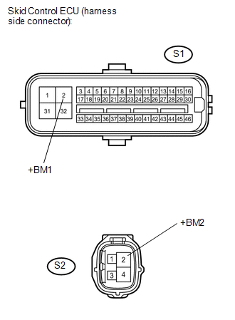
(b) Measure the voltage.
Standard Voltage:
|
Tester Connection |
Specified Condition |
|---|---|
|
S1-2 (+BM1) - Body ground |
10 to 14 V |
|
S2-2 (+BM2) - Body ground |
10 to 14 V |
(c) Reconnect the skid control ECU (master cylinder solenoid) connectors.
| NG | |
REPAIR OR REPLACE HARNESS OR CONNECTOR (+BM1 AND +BM2 CIRCUIT) |
|
|
4. |
CHECK HARNESS AND CONNECTOR (SKID CONTROL ECU - BODY GROUND) |
|
(a) Disconnect the skid control ECU (master cylinder solenoid) connectors. |
|
.png)
(b) Measure the resistance.
Standard Resistance:
|
Tester Connection |
Specified Condition |
|---|---|
|
S1-1 (GND1) - Body ground |
Below 1 Ω |
|
S1-32 (GND2) - Body ground |
Below 1 Ω |
|
S2-4 (GND3) - Body ground |
Below 1 Ω |
(c) Reconnect the skid control ECU (master cylinder solenoid) connectors.
| NG | |
REPAIR OR REPLACE HARNESS OR CONNECTOR (GND CIRCUIT) |
|
|
5. |
RECONFIRM DTC |
(a) Clear the DTCs (See page
).
(b) Turn the ignition switch to OFF.
(c) Depress the brake pedal more than 20 times.
(d) Turn the ignition switch to the ON position.
(e) Wait until the pump motor stops.
(f) Depress the brake pedal several times until the pump motor is turned on.
(g) Wait until the pump stops.
(h) Repeat (f) and (g) three times.
(i) Check if the same DTCs are recorded.
|
Result |
Proceed to |
|---|---|
|
DTC output |
A |
|
DTC not output |
B |
| A | |
REPLACE HYDRAULIC BRAKE BOOSTER |
| B | |
END |
 Brake Booster Pump Motor on Time Abnormally Long (C1252)
DESCRIPTION
The motor relay (semiconductor relay) is built into the master cylinder solenoid
and drives the pump motor based on a signal from the skid control ECU (master cylinder
solenoid).
...
 Pressure Sensor or Switch (C1254)
DESCRIPTION
The accumulator pressure sensor is connected to the skid control ECU in the master
cylinder solenoid.
DTC No.
DTC Detecting Condition
Trouble Areas
...
Other materials:
Rear Speed Sensor RH Malfunction (C1403,C1404)
DESCRIPTION
The speed sensor detects wheel speed and sends the appropriate signals to the
skid control ECU (brake actuator assembly). These signals are used for brake control.
The speed sensor rotors have rows of alternating N and S magnetic poles and their
magnetic fields change when the roto ...
Door Control Receiver
Components
COMPONENTS
ILLUSTRATION
Removal
REMOVAL
PROCEDURE
1. REMOVE ROOF HEADLINING ASSEMBLY (for Double Cab)
(See page )
2. REMOVE ROOF HEADLINING ASSEMBLY (for Access Cab)
(See page )
3. REMOVE DOOR CONTROL RECEIVER (w/o Tire Pressure Warning System)
(a) Disconne ...
Precaution
PRECAUTION
1. PRECAUTIONS WHEN CHECKING FOR DTCS
(a) When the cable is disconnected from the negative (-) battery terminal, the
DTCs stored in the steering lock ECU (steering lock actuator or UPR bracket assembly)
are cleared. Be sure to record any output DTCs immediately.
(b) Normally, with ...
