Toyota Tacoma (2015-2018) Service Manual: Parts Location
PARTS LOCATION
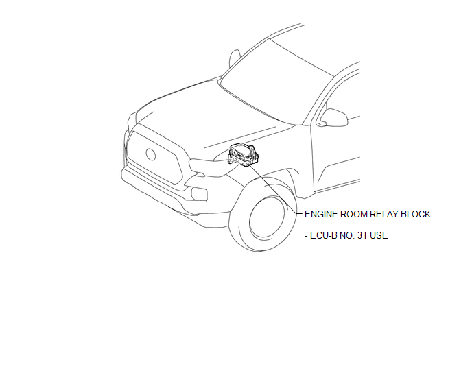
ILLUSTRATION
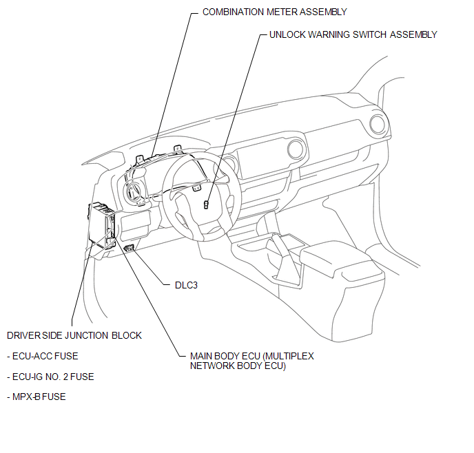
ILLUSTRATION
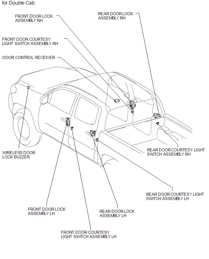
ILLUSTRATION
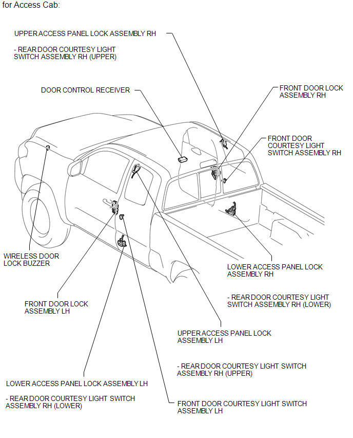
ILLUSTRATION
 Precaution
PRECAUTION
1. DOOR CONTROL RECEIVER EXPRESSIONS
(a) The type of door control receiver used on this model differs according to
the specifications of the vehicle. The expressions listed in the table ...
 System Description
SYSTEM DESCRIPTION
1. WIRELESS DOOR LOCK CONTROL SYSTEM
The wireless door lock control system functions to lock and unlock all the doors
from a distance. The system is controlled by a door control ...
Other materials:
Disassembly
DISASSEMBLY
PROCEDURE
1. REMOVE FRONT LOWER ARM BUSH NO. 1
(a) Using a hammer and chisel, raise the flange of the bush diagonally as shown
in the illustration.
(b) Using SST, remove the lower arm bush.
SST: 09950-40011
09951-04010
09952-04010
09953-04020
09954-04010 ...
Engine Hood Courtesy Switch
Components
COMPONENTS
ILLUSTRATION
Inspection
INSPECTION
PROCEDURE
1. INSPECT HOOD COURTESY SWITCH (HOOD LOCK ASSEMBLY)
(a) Check the resistance.
(1) Measure the resistance according to the value(s) in the table below.
Text in Illustration
*a
...
System Diagram
SYSTEM DIAGRAM
Transmitting ECU (Transmitter)
Receiving ECU
Signal
Communication Method
4 wheel drive control ECU
Skid control ECU (Brake actuator assembly)
Rear differential lock status signal
H ...
