Toyota Tacoma (2015-2018) Service Manual: Parts Location
PARTS LOCATION
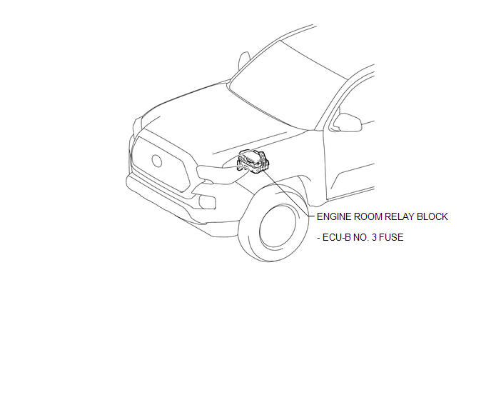
ILLUSTRATION
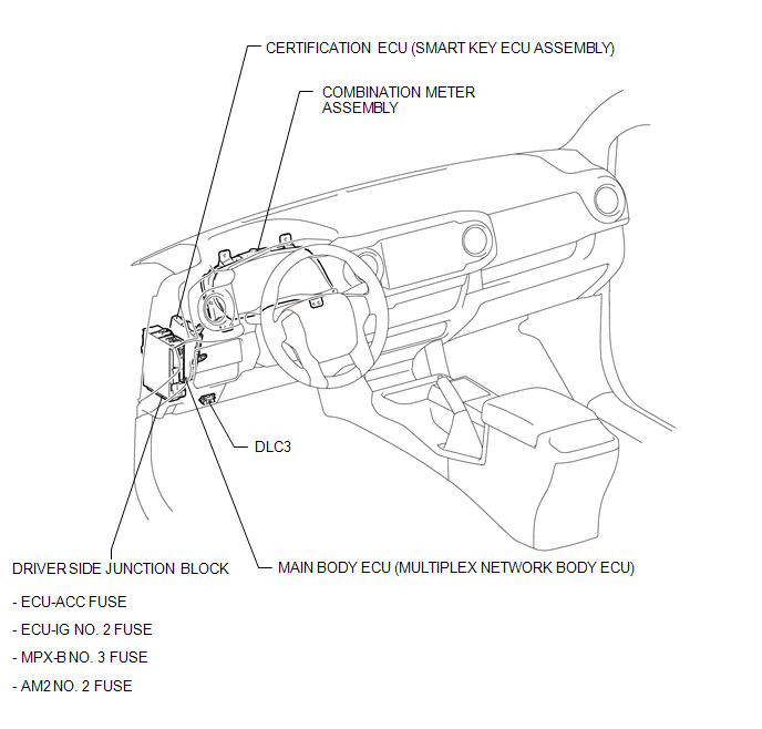
ILLUSTRATION
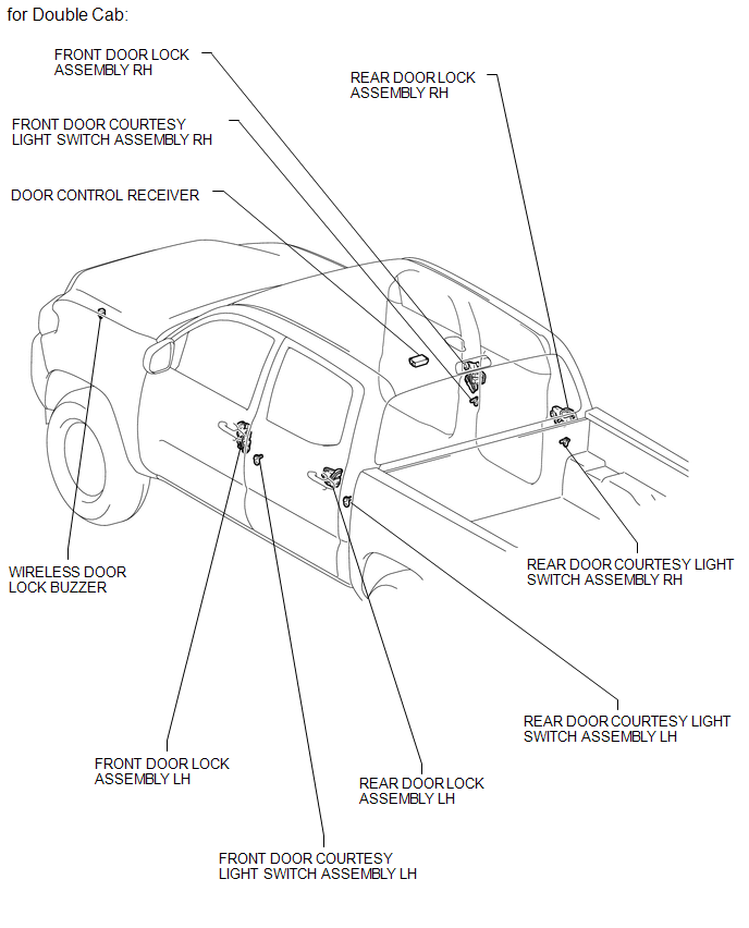
ILLUSTRATION
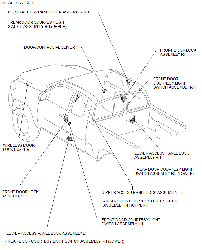
ILLUSTRATION

 Precaution
PRECAUTION
1. PRECAUTIONS WHEN USING TECHSTREAM
(a) When using the Techstream with the engine switch off to troubleshoot:
Connect the Techstream to the vehicle, and turn a courtesy light switch on ...
Other materials:
Replacement
REPLACEMENT
PROCEDURE
1. REPLACE INTAKE VALVE GUIDE BUSH
(a) Heat the cylinder head to 80 to 100┬░C (176 to 212┬░F).
(b) Place the cylinder head on wooden blocks.
(c) Using SST and a hammer, tap out the intake valve guide bushes.
SST: 09201-10000
09201-01050
SST: 09950-70010 ...
Transmission Range Sensor "A" Circuit Open (P070513,P070562)
DESCRIPTION
The park/neutral position switch detects the shift lever position and sends signals
to the ECM.
DTC No.
DTC Detection Condition
Trouble Area
SAE
P070513
All of the following signals are OFF simultaneously for 60 ...
On-vehicle Inspection
ON-VEHICLE INSPECTION
PROCEDURE
1. INSPECT REAR AIRBAG SENSOR (for Vehicle not Involved in Collision)
(a) Perform a diagnostic system check (See page
).
2. INSPECT REAR AIRBAG SENSOR (for Vehicle Involved in Collision and Airbag has
not Deployed)
CAUTION:
For rear airbag sensor removal and ...
