Toyota Tacoma (2015-2018) Service Manual: Parts Location
PARTS LOCATION
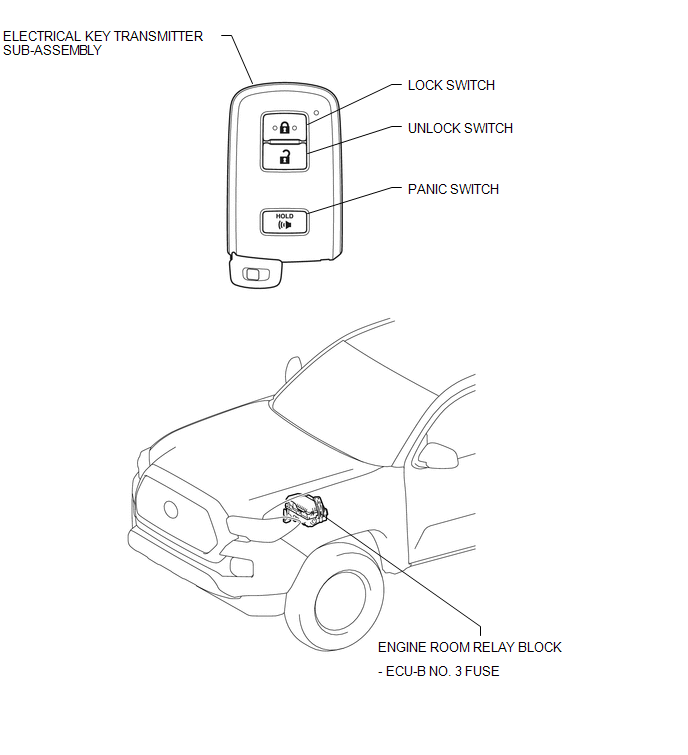
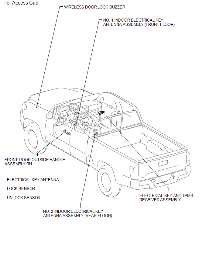
ILLUSTRATION
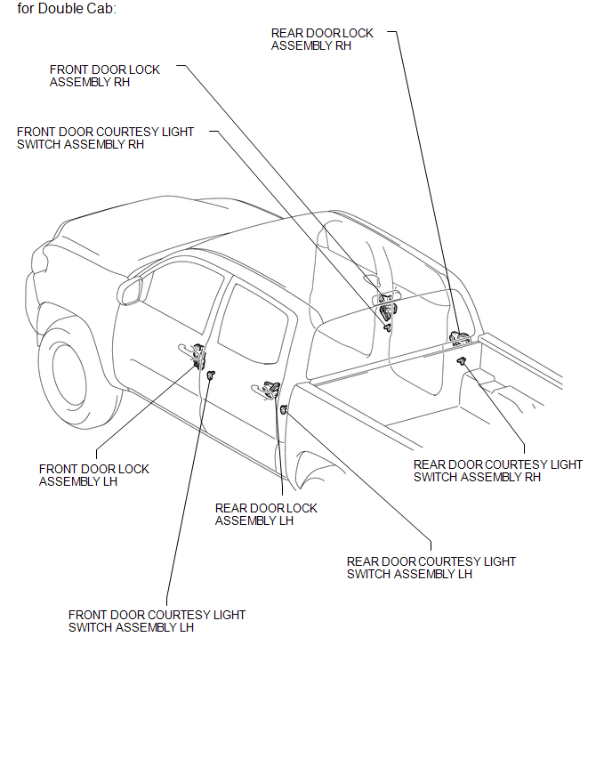
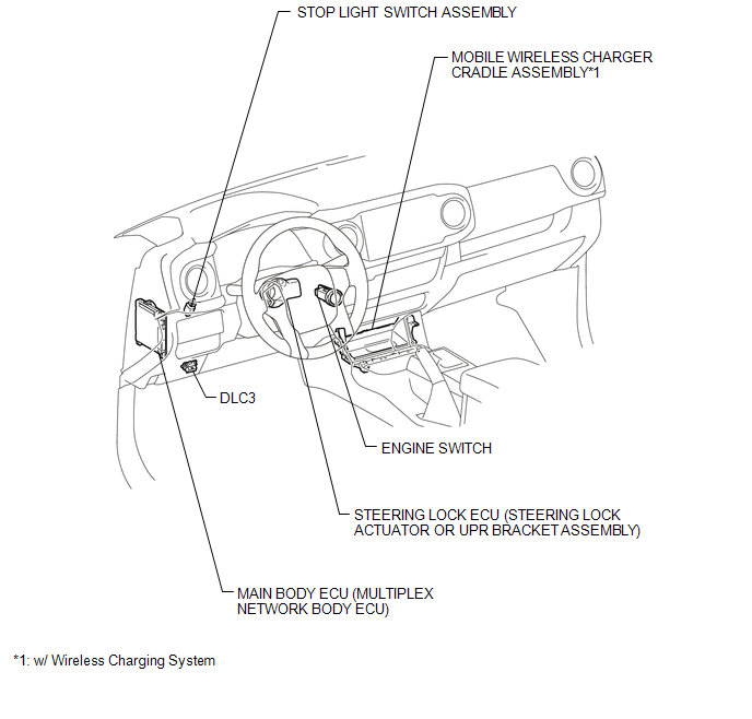
ILLUSTRATION
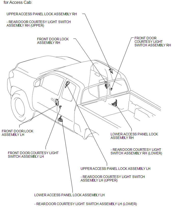
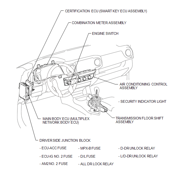
ILLUSTRATION
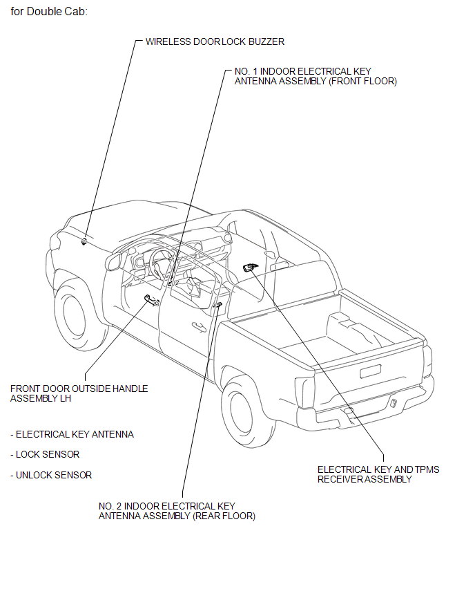
ILLUSTRATION
ILLUSTRATION
ILLUSTRATION
ILLUSTRATION

 Precaution
PRECAUTION
1. CAUTION REGARDING INTERFERENCE WITH ELECTRONIC DEVICES
CAUTION:
People with implantable cardiac pacemakers, cardiac resynchronization
therapy-pacemakers or implantable car ...
Other materials:
Disassembly
DISASSEMBLY
CAUTION / NOTICE / HINT
HINT:
The procedure described below is for the LH side. Use the same procedure for
both the LH and RH sides, unless otherwise specified.
PROCEDURE
1. REMOVE REAR SEATBACK COVER
(a) Remove the 2 screws.
...
Noise Occurs or Sound Skips when Portable Player Plays
CAUTION / NOTICE / HINT
HINT:
Perform this check with the portable player volume set at an appropriate
level.
Make sure that there are no obstructions between the portable player
and radio and display receiver assembly that may block signals, and that
the portable player an ...
Front Airbag Sensor RH Circuit Malfunction (B1610/13)
DESCRIPTION
The front airbag sensor RH consists of parts such as the diagnostic circuit and
the frontal detection sensor.
When the airbag sensor assembly receives signals from the frontal deceleration
sensor, it determines whether or not the SRS should be activated.
DTC B1610/13 is set when a ...
