Toyota Tacoma (2015-2018) Service Manual: Check Bus 3 Line for Short to +B
DESCRIPTION
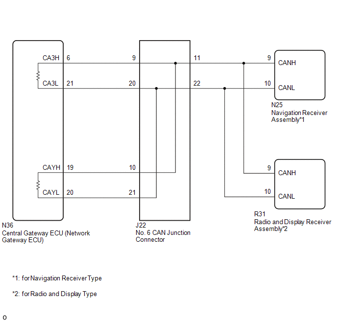
There may be a short circuit between one of the CAN bus lines and +B when no resistance exists between terminal 6 (CA3H) of the central gateway ECU (network gateway ECU) and terminal 16 (BAT) of the DLC3, or terminal 21 (CA3L) of the central gateway ECU (network gateway ECU) and terminal 16 (BAT) of the DLC3.
|
Detection Item |
Trouble Area |
|---|---|
|
No resistance exists between terminal 6 (CA3H) of the central gateway ECU (network gateway ECU) and terminal 16 (BAT) of the DLC3, or terminal 21 (CA3L) of the central gateway ECU (network gateway ECU) and terminal 16 (BAT) of the DLC3. |
|
- *1: for Navigation Receiver Type
- *2: for Radio and Display Type
WIRING DIAGRAM
CAUTION / NOTICE / HINT
CAUTION:
When performing the confirmation driving pattern, obey all speed limits and traffic laws.
NOTICE:
- Because the order of diagnosis is important to allow correct diagnosis,
make sure to begin troubleshooting using How to Proceed with Troubleshooting
when CAN communication system related DTCs are output.
Click here
.gif)
- Before measuring the resistance of the CAN bus, turn the ignition switch off and leave the vehicle for 1 minute or more without operating the key or any switches, or opening or closing the doors. After that, disconnect the cable from the negative (-) battery terminal and leave the vehicle for 1 minute or more before measuring the resistance.
- After turning the ignition switch off, waiting time may be required
before disconnecting the cable from the negative (-) battery terminal. Therefore,
make sure to read the disconnecting the cable from the negative (-) battery
terminal notices before proceeding with work.
Click here
- Some parts must be initialized and set when replacing or removing and
installing parts.
Click here
- After performing repairs, perform the DTC check procedure and confirm
that the DTCs are not output again.
DTC check procedure: Turn the ignition switch to ON and wait for 1 minute or more. Then operate the suspected malfunctioning system and drive the vehicle at 60 km/h (37 mph) or more for 5 minutes or more.
- After the repair, perform the CAN bus check and check that all the ECUs
and sensors connected to the CAN communication system are displayed as normal.
Click here
HINT:
- Before disconnecting related connectors for inspection, push in on each connector body to check that the connector is not loose or disconnected.
- When a connector is disconnected, check that the terminals and connector body are not cracked, deformed or corroded.
PROCEDURE
|
1. |
CHECK FOR SHORT TO +B IN CAN BUS LINE (NO. 6 CAN JUNCTION CONNECTOR) |
(a) Disconnect the cable from the negative (-) battery terminal.
(b) Disconnect the No. 6 CAN junction connector.
(c) Measure the resistance according to the value(s) in the table below.
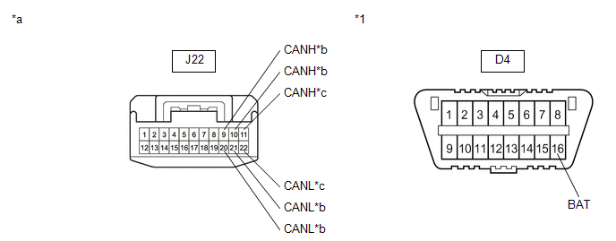 Text in Illustration
|
*1 |
DLC3 |
- |
- |
|
*a |
Front view of wire harness connector (to No. 6 CAN Junction Connector) |
*b |
to Central Gateway ECU (Network Gateway ECU) |
|
*c |
to Navigation Receiver Assembly (for Navigation Receiver Type) or Radio and Display Receiver Assembly (for Radio and Display Type) |
- |
- |
Standard Resistance:
|
Tester Connection |
Condition |
Specified Condition |
Connected to |
|---|---|---|---|
|
J22-9 (CANH) - D4-16 (BAT) |
Cable disconnected from negative (-) battery terminal |
6 kΩ or higher |
Central gateway ECU (network gateway ECU) |
|
J22-20 (CANL) - D4-16 (BAT) |
|||
|
J22-10 (CANH) - D4-16 (BAT) |
Cable disconnected from negative (-) battery terminal |
6 kΩ or higher |
Central gateway ECU (network gateway ECU) |
|
J22-21 (CANL) - D4-16 (BAT) |
|||
|
J22-11 (CANH) - D4-16 (BAT) |
Cable disconnected from negative (-) battery terminal |
6 kΩ or higher |
Navigation receiver assembly*1 or Radio and display receiver assembly*2 |
|
J22-22 (CANL) - D4-16 (BAT) |
- *1: for Navigation Receiver Type
- *2: for Radio and Display Type
|
Result |
Proceed to |
|---|---|
|
OK |
A |
|
NG (Central gateway ECU (network gateway ECU) CAN main line) |
B |
|
NG (ECU or sensor CAN branch lines) |
C |
| A | .gif) |
REPLACE NO. 6 CAN JUNCTION CONNECTOR |
| C | |
GO TO STEP 3 |
|
.gif)
|
2. |
CHECK FOR SHORT TO +B IN CAN BUS LINE (NO. 6 CAN JUNCTION CONNECTOR - CENTRAL GATEWAY ECU (NETWORK GATEWAY ECU)) |
(a) Disconnect the N36 central gateway ECU (network gateway ECU) connector.
(b) Measure the resistance according to the value(s) in the table below.
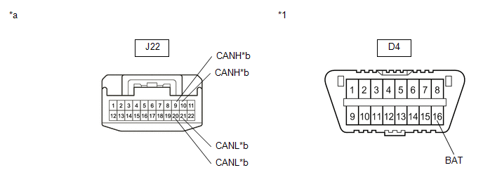 Text in Illustration
|
*1 |
DLC3 |
- |
- |
|
*a |
Front view of wire harness connector (to No. 6 CAN Junction Connector) |
*b |
to Central Gateway ECU (Network Gateway ECU) |
Standard Resistance:
|
Tester Connection |
Condition |
Specified Condition |
|---|---|---|
|
J22-9 (CANH) - D4-16 (BAT) |
Cable disconnected from negative (-) battery terminal |
6 kΩ or higher |
|
J22-20 (CANL) - D4-16 (BAT) |
||
|
J22-10 (CANH) - D4-16 (BAT) |
Cable disconnected from negative (-) battery terminal |
6 kΩ or higher |
|
J22-21 (CANL) - D4-16 (BAT) |
| OK | |
REPLACE CENTRAL GATEWAY ECU (NETWORK GATEWAY ECU) |
| NG | |
REPAIR OR REPLACE CAN MAIN BUS LINE OR CONNECTOR (NO. 6 CAN JUNCTION CONNECTOR - CENTRAL GATEWAY ECU (NETWORK GATEWAY ECU)) |
|
3. |
CHECK FOR SHORT TO B+ IN CAN BUS LINES (ECU, SENSOR) |
|
(a) Reconnect the CAN junction connector. |
|
(b) Disconnect the connector that includes terminals CANH and CANL from the ECU or sensor to which the bus line shorted to +B is connected
(c) Measure the resistance according to the value(s) in the table below.
Standard Resistance:
|
Tester Connection |
Condition |
Specified Condition |
|---|---|---|
|
N36-6 (CA3H) - D4-16 (BAT) |
Cable disconnected from negative (-) battery terminal |
6 kΩ or higher |
|
N36-21 (CA3L) - D4-16 (BAT) |
Cable disconnected from negative (-) battery terminal |
6 kΩ or higher |
|
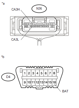
*a |
Component with harness connected (Central Gateway ECU (Network Gateway ECU)) |
|
*b |
Front view of DLC3 |
HINT:
If the resistance changes to 6 kΩ or higher when the connector is disconnected from the ECU or sensor, there may be a short in the ECU or sensor.
| OK | |
REPLACE ECU OR SENSOR |
| NG | |
REPAIR OR REPLACE HARNESS OR CONNECTOR |
 Open in One Side of Bus 2 Branch Line
DESCRIPTION
When the CAN bus main lines are normal (no open, short to ground, short to +B
or short between lines) and there is an ECU or sensor on the "Communication Bus
Check" screen t ...
 Check Bus 3 Lines for Short Circuit
DESCRIPTION
There may be a short circuit between the CAN main bus lines and/or CAN branch
lines when the resistance between terminals 6 (CA3H) and 21 (CA3L) of the central
gateway ECU (network ga ...
Other materials:
Tonneau Cover Assembly
Removal
REMOVAL
PROCEDURE
1. REMOVE TOP COVER SUB-ASSEMBLY
(a) Open the cover.
(b) Remove the bolt and top cover sub-assembly.
2. REMOVE REAR BODY SIDE PANEL PROTECTOR
Click here
Installation
INSTALLATION
PROCEDURE
1. INSTALL REAR ...
Installation
INSTALLATION
PROCEDURE
1. INSTALL FRONT CONSOLE BOX (for Automatic Transmission)
(a) When installing a new front console box:
Text in Illustration
*a
Runner Portion
*b
Cut Off
(1) Usin ...
Freeze Frame Data
FREEZE FRAME DATA
CHECK FREEZE FRAME DATA
HINT:
The ECU records vehicle and driving condition information as freeze frame data
the moment a DTC is stored.
(a) Connect the Techstream to the DLC3.
(b) Turn the ignition switch to ON.
(c) Turn the Techstream on.
(d) Enter the following menus: P ...
