Toyota Tacoma (2015-2018) Service Manual: Parts Location
PARTS LOCATION
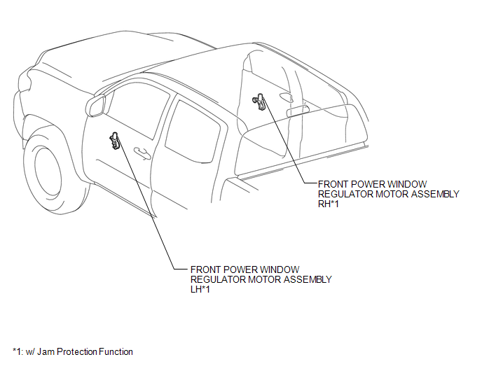
ILLUSTRATION
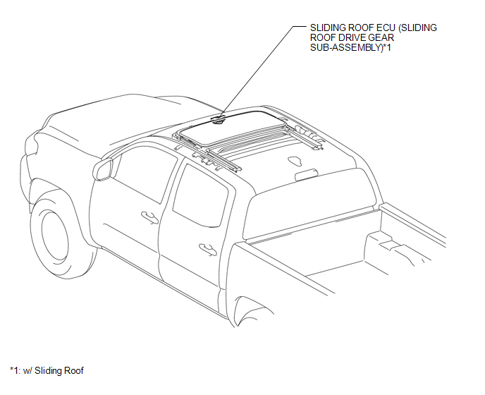
ILLUSTRATION
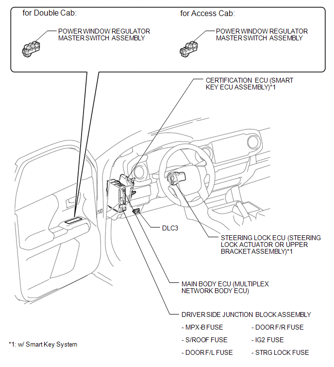
ILLUSTRATION
 Precaution
PRECAUTION
1. EXPRESSIONS OF IGNITION SWITCH
HINT:
The type of ignition switch used on this model differs according to the specifications
of the vehicle. The expressions listed in the table below ...
 System Description
SYSTEM DESCRIPTION
1. LIN COMMUNICATION SYSTEM DESCRIPTION
The LIN communication system is used for communication between the components
in the tables below. If communication cannot be performed t ...
Other materials:
Removal
REMOVAL
PROCEDURE
1. REMOVE INSTRUMENT PANEL LOWER FINISH PANEL SUB-ASSEMBLY
(See page )
2. REMOVE DRIVER SIDE JUNCTION BLOCK
(a) Disconnect the 5 connectors on the front side.
(b) Remove the 2 nuts to separate the driver side j ...
Torque Converter Clutch Circuit Short to Battery or Open (P074015)
DESCRIPTION
Shift solenoid valve SL is turned on and off by signals from the ECM to control
the hydraulic pressure acting on the lock-up relay valve, which then controls operation
of the lock-up clutch.
DTC No.
DTC Detection Condition
Trouble Area
SA ...
Problem Symptoms Table
PROBLEM SYMPTOMS TABLE
HINT:
Use the table below to help determine the cause of problem symptoms.
If multiple suspected areas are listed, the potential causes of the symptoms
are listed in order of probability in the "Suspected Area" column of the
table. Check each sy ...
