Toyota Tacoma (2015-2018) Service Manual: Operation Check
OPERATION CHECK
1. CHECK WIRELESS CHARGING SYSTEM OPERATION
(a) Turn the ignition switch ON (IG or ACC).
(b) Press the mobile wireless charger switch and check that the switch indicator light illuminates.
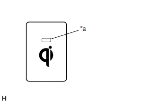 Text in Illustration
|
*a |
Switch Indicator Light |
(c) Place a rechargeable device on the charging area and check that the indicator light (amber) illuminates, indicating a charge is in progress.
.png) Text in Illustration
Text in Illustration
|
*a |
Indicator Light (Green) |
|
*b |
Indicator Light (Amber) |
|
*c |
Charging Area |
(d) Check that the indicator lights (amber and green) are illuminated when charging is complete.
HINT:
- Some phones, cases or cover type wireless chargers may not cause the green indicator to illuminate even though it is fully charged.
- Check the mobile device to confirm charge status.
HINT:
Please refer to precaution for the details (See page
.gif) ).
).
 How To Proceed With Troubleshooting
CAUTION / NOTICE / HINT
HINT:
Use the following procedure to troubleshoot the wireless charging system.
PROCEDURE
1.
VEHICLE BROUGHT TO WORKSHOP
...
 Problem Symptoms Table
PROBLEM SYMPTOMS TABLE
HINT:
Use the table below to help determine the cause of problem symptoms.
If multiple suspected areas are listed, the potential causes of the symptoms
are lis ...
Other materials:
Deck Light Relay
Inspection
INSPECTION
PROCEDURE
1. REMOVE DECK LIGHT RELAY
(a) Check the resistance.
(1) Measure the resistance according to the value(s) in the table below.
Standard:
Tester Connection
Condition
Specified Condition
...
While Alarm is Armed, Battery is Reconnected but Alarm does not Sound
DESCRIPTION
While the alarm is armed, the EEPROM inside the main body ECU (multiplex network
body ECU) will remember the armed state even if the battery is disconnected, and
the alarm will sound when the battery is reconnected.
If the alarm does not sound when the battery is reconnected, the a ...
Installation
INSTALLATION
CAUTION / NOTICE / HINT
HINT:
Use the same procedure for both the RH and LH sides.
The procedure described below is for the LH side.
PROCEDURE
1. INSTALL CURTAIN SHIELD AIRBAG ASSEMBLY
(a) Insert the 5 hooks, install 6 new bolts, 2 new clips with pins and 2 new
...
