Toyota Tacoma (2015-2018) Service Manual: Open in Pump Motor Circuit (C1251)
DESCRIPTION
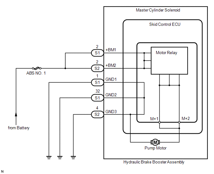
The motor relay (semiconductor relay) is built into the master cylinder solenoid and drives the pump motor based on a signal from the skid control ECU (master cylinder solenoid).
|
DTC No. |
DTC Detecting Condition |
Trouble Areas |
|---|---|---|
|
C1251 |
Open in motor system circuit (motor input circuit) |
Hydraulic brake booster pump motor circuit |
WIRING DIAGRAM
CAUTION / NOTICE / HINT
HINT:
Remove the hydraulic brake booster before the inspection (See page
.gif) ).
).
PROCEDURE
|
1. |
CHECK BRAKE PUMP MOTOR WIRE HARNESS CONNECTION (MT+ / MT-) |
(a) Using a screwdriver, remove the 2 plugs from the hydraulic brake booster
(See page ).
(b) Check the tightening torque of 2 screws which fasten the wire harness connecting
hydraulic brake booster and brake booster pump (See page
).
Torque:
2.9 N·m {30 kgf·cm, 26 in·lbf}
| NG | .gif) |
RETIGHTEN SCREWS |
|
.gif)
|
2. |
CHECK RESISTANCE OF PUMP MOTOR WIRE HARNESS (MT+/MT-) |
|
(a) Using a screwdriver, remove the 2 screws and pull the wire harness from the hydraulic brake booster. |
|
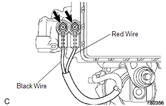
(b) Measure the resistance between the red wire (MT+) and black wire (MT-).
Resistance:
2 Ω
| NG | |
REPLACE HYDRAULIC BRAKE BOOSTER |
|
|
3. |
RECONFIRM DTC |
(a) Reassemble the hydraulic brake booster, then reinstall the hydraulic brake booster.
(b) Clear the DTCs (See page
).
(c) Check if the same DTCs are detected.
|
Result |
Proceed to |
|---|---|
|
DTC output |
A |
|
DTC not output |
B |
| A | |
REPLACE MASTER CYLINDER SOLENOID |
| B | |
END |
 Open Circuit in IG1/IG2 Power Source Circuit (C1242)
DESCRIPTION
If there is a problem with the skid control ECU (master cylinder solenoid) power
supply circuit, the skid control ECU outputs the DTC and prohibits operation under
the fail safe funct ...
 Brake Booster Pump Motor on Time Abnormally Long (C1252)
DESCRIPTION
The motor relay (semiconductor relay) is built into the master cylinder solenoid
and drives the pump motor based on a signal from the skid control ECU (master cylinder
solenoid).
...
Other materials:
Data List / Active Test
DATA LIST / ACTIVE TEST
1. DATA LIST
NOTICE:
In the table below, the values listed under "Normal Condition" are reference
values. Do not depend solely on these reference values when deciding whether a part
is faulty or not.
HINT:
Using the Techstream to read the Data List allows t ...
Tire Pressure Warning Light Circuit
DESCRIPTION
If the tire pressure warning ECU and receiver detects any problems, the tire
pressure warning light blinks for 1 minute then illuminates, and tire pressure monitoring
is disabled at the same time. At this time, the ECU stores a DTC in memory.
Connecting terminals TC and CG of the D ...
Road Test
ROAD TEST
1. PROBLEM SYMPTOM CONFIRMATION
(a) Based on the result of the customer problem analysis, try to reproduce the
symptoms. If the problem is that the transmission does not shift up or down, or
that the shift point is too high or too low, conduct the following road test referring
to t ...
