Toyota Tacoma (2015-2018) Service Manual: Open Circuit in IG1/IG2 Power Source Circuit (C1242)
DESCRIPTION
If there is a problem with the skid control ECU (master cylinder solenoid) power supply circuit, the skid control ECU outputs the DTC and prohibits operation under the fail safe function.
If the voltage supplied to terminal IG1 and/or IG2 is not within the DTC detection threshold due to malfunctions in parts such as the battery or alternator circuit, this DTC is stored.
|
DTC No. |
DTC Detecting Condition |
Trouble Areas |
|---|---|---|
|
C1242 |
Vehicle speed 3 km/h (1.9 mph) or more and voltage of skid control ECU (master cylinder solenoid) terminal IG1 and/or IG2 remains at below 6.5 V for more than 7 seconds. |
|
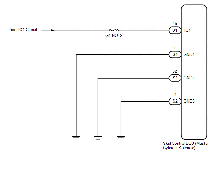
WIRING DIAGRAM
CAUTION / NOTICE / HINT
NOTICE:
- When replacing the skid control ECU (master cylinder solenoid), perform
zero point calibration (See page
.gif) ).
). - Inspect the fuses for circuits related to this system before performing the following inspection procedure.
PROCEDURE
|
1. |
INSPECT BATTERY |
(a) Check the battery voltage.
Standard Voltage:
11 to 14 V
| NG | .gif) |
GO TO CHARGING SYSTEM |
|
.gif)
|
2. |
CHECK HARNESS AND CONNECTOR (IG2 TERMINAL) |
|
(a) Disconnect the skid control ECU (master cylinder solenoid) connector. |
|
(b) Turn the ignition switch to the ON position.
(c) Measure the voltage.
Standard Voltage:
|
Tester Connection |
Specified Condition |
|---|---|
|
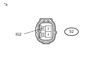
S2-1 (IG2) - Body ground |
10 to 14 V |
|
*a |
Front view of wire harness connector (to Skid Control ECU (Master Cylinder Solenoid)) |
(d) Reconnect the skid control ECU (master cylinder solenoid) connector.
(e) Turn the ignition switch to OFF.
| NG | |
REPAIR OR REPLACE HARNESS OR CONNECTOR |
|
|
3. |
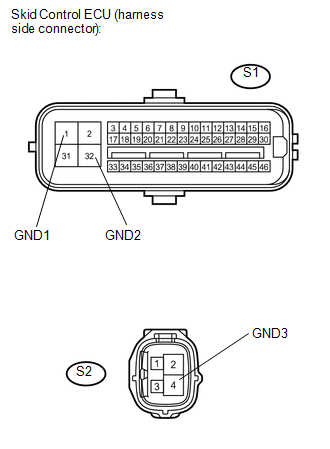
CHECK HARNESS AND CONNECTOR (GND TERMINAL) |
|
(a) Disconnect the skid control ECU (master cylinder solenoid) connectors. |
|
(b) Measure the resistance.
Standard Resistance:
|
Tester Connection |
Specified Condition |
|---|---|
|
S1-1 (GND1) - Body ground |
Below 1 Ω |
|
S1-32 (GND2) - Body ground |
Below 1 Ω |
|
S2-4 (GND3) - Body ground |
Below 1 Ω |
(c) Reconnect the skid control ECU (master cylinder solenoid) connectors.
| NG | |
REPAIR OR REPLACE HARNESS OR CONNECTOR |
|
|
4. |
RECONFIRM DTC |
(a) Clear the DTCs (See page
).
(b) Drive the vehicle at a speed of 3 km/h (1.9 mph) or more for 7 seconds or more.
(c) Check if the same DTCs are detected.
|
Result |
Proceed to |
|---|---|
|
DTC output |
A |
|
DTC not output |
B |
| A | |
REPLACE MASTER CYLINDER SOLENOID |
| B | |
END |
 Low Power Supply Voltage Malfunction (C1241)
DESCRIPTION
If there is a problem with the skid control ECU (master cylinder solenoid) power
supply circuit, the skid control ECU outputs the DTC and prohibits operation under
the fail-safe funct ...
 Open in Pump Motor Circuit (C1251)
DESCRIPTION
The motor relay (semiconductor relay) is built into the master cylinder solenoid
and drives the pump motor based on a signal from the skid control ECU (master cylinder
solenoid).
...
Other materials:
Removal
REMOVAL
PROCEDURE
1. REMOVE NO. 2 ENGINE UNDER COVER SUB-ASSEMBLY (w/ Off Road Package)
2. REMOVE NO. 1 ENGINE UNDER COVER SUB-ASSEMBLY
3. DRAIN ENGINE COOLANT
4. REMOVE RADIATOR GRILLE
(See page )
5. REMOVE EXHAUST MANIFOLD SUB-ASSEMBLY RH
(See page )
6. REMOVE NO. 2 OIL COOLER INLET ...
Removal
REMOVAL
PROCEDURE
1. REMOVE LOWER STEERING COLUMN COVER
2. REMOVE UPPER STEERING COLUMN COVER
3. REMOVE WINDSHIELD WIPER SWITCH ASSEMBLY
(a) Disconnect the 2 connectors.
Text in Illustration
*a
Protective Tape
...
Check Bus 5 Line for Short to +B
DESCRIPTION
There may be a short circuit between one of the CAN bus lines and +B when no
resistance exists between terminal 15 (CA5H) of the central gateway ECU (network
gateway ECU) and terminal 16 (BAT) of the DLC3, or terminal 16 (CA5L) of the central
gateway ECU (network gateway ECU) and ...
