Toyota Tacoma (2015-2018) Service Manual: Open in Outer Mirror Indicator(Slave) (C1AB5)
DESCRIPTION
This DTC is stored when the blind spot monitor sensor RH detects an open in the blind spot monitor indicator RH.
|
DTC Code |
DTC Detection Condition |
Trouble Area |
|---|---|---|
|
C1AB5 |
With the blind spot monitor main switch assembly (warning canceling switch assembly) on, the current flowing to the indicator is below a specified value when indicator operation voltage is sent to the indicator. |
|
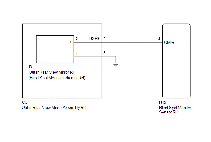
WIRING DIAGRAM
CAUTION / NOTICE / HINT
NOTICE:
When checking for DTCs, make sure that the blind spot monitor main switch assembly (warning canceling switch assembly) is on.
PROCEDURE
|
1. |
CHECK DTC |
(a) Clear the DTCs (See page .gif) ).
).
(b) Recheck for DTCs and check if the same DTC is output again (See page
).
OK:
No DTCs are output.
| OK | .gif) |
USE SIMULATION METHOD TO CHECK |
|
.gif)
|
2. |
CHECK HARNESS AND CONNECTOR (OUTER REAR VIEW MIRROR ASSEMBLY RH - BLIND SPOT MONITOR SENSOR RH AND BODY GROUND) |
(a) Disconnect the B13 blind spot monitor sensor RH connector.
(b) Disconnect the O3 outer rear view mirror assembly RH connector.
(c) Measure the resistance according to the value(s) in the table below.
Standard Resistance:
|
Tester Connection |
Condition |
Specified Condition |
|---|---|---|
|
B13-4 (OMIR) - O3-1 (BSR+) |
Always |
Below 1 Ω |
|
O3-8 - Body ground |
Always |
Below 1 Ω |
| NG | |
REPAIR OR REPLACE HARNESS OR CONNECTOR |
|
|
3. |
INSPECT OUTER REAR VIEW MIRROR ASSEMBLY RH |
(a) Remove the outer rear view mirror assembly RH (See page
).
(b) Remove the outer rear view mirror RH (See page
).
(c) Measure the resistance according to the value(s) in the table below.
Standard Resistance:
|
Tester Connection |
Condition |
Specified Condition |
|---|---|---|
|
O3-1 (BSR+) - B-2 (+) |
Always |
Below 1 Ω |
|
O3-8 - B-1 (-) |
Always |
Below 1 Ω |
| NG | |
REPLACE OUTER REAR VIEW MIRROR ASSEMBLY RH |
|
|
4. |
CHECK OUTER REAR VIEW MIRROR RH |
(a) Replace the outer rear view mirror RH with a new or normally functioning
one (See page ).
(b) Clear the DTCs (See page ).
(c) Recheck for DTCs and check if the same DTC is output again (See page
).
OK:
No DTCs are output.
| OK | |
END (OUTER REAR VIEW MIRROR RH WAS DEFECTIVE) |
| NG | |
REPLACE BLIND SPOT MONITOR SENSOR RH |
 Blind Spot Monitor Slave Module (C1AB7)
DESCRIPTION
This DTC is stored when the blind spot monitor sensor RH detects an internal
malfunction.
DTC Code
DTC Detection Condition
Trouble Area
...
 Blind Spot Monitor Master Module (C1AB6)
DESCRIPTION
This DTC is stored when the blind spot monitor sensor LH detects an internal
malfunction.
DTC Code
DTC Detection Condition
Trouble Area
...
Other materials:
Disposal
DISPOSAL
PROCEDURE
1. DISPOSE OF BRAKE BOOSTER ACCUMULATOR ASSEMBLY
(a) Place the brake booster accumulator in a vise and cover it with a cloth.
(b) Slowly cut a hole on the brake booster accumulator side in the A portion
shown in the illustration on the left. And discharge the gas and liqui ...
Confirm Cellular Phone Functionality
PROCEDURE
1.
CHECK THE CUSTOMER'S CELLULAR PHONE COMPATIBILITY
(a) Go to TIS "Bluetooth" Compatibility Portal and check if the cellular phone
is compatible.
Result
Result
Proceed to
Cellular phone is compatibl ...
Rear Differential Lock Position SW Stuck OFF (P17BB)
DESCRIPTION
This DTC is output when an OFF malfunction of the differential lock indicator
switch is detected.
DTC No.
Detection Item
DTC Detection Condition
Trouble Area
P17BB
Rear Differential Lock Position SW Stuck OFF
...
