Toyota Tacoma (2015-2018) Service Manual: Components
COMPONENTS
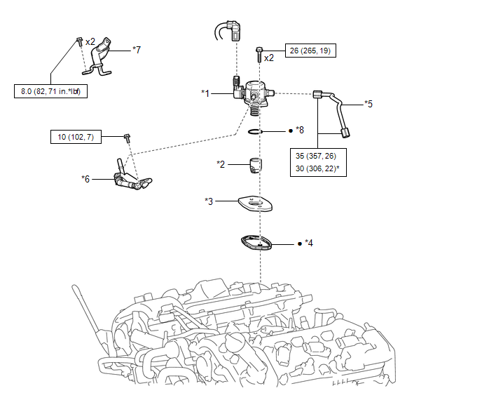
ILLUSTRATION
|
*1 |
FUEL PUMP ASSEMBLY |
*2 |
FUEL PUMP LIFTER ASSEMBLY |
|
*3 |
FUEL PUMP LIFTER GUIDE |
*4 |
FUEL PUMP SPACER GASKET |
|
*5 |
NO. 1 FUEL PIPE SUB-ASSEMBLY |
*6 |
FUEL TUBE SUB-ASSEMBLY |
|
*7 |
WIRE HARNESS CLAMP BRACKET |
*8 |
O-RING |
.png) |
N*m (kgf*cm, ft.*lbf): Specified torque |
* |
For use with union nut wrench |
|
â—Ź |
Non-reusable part |
- |
- |

 On-vehicle Inspection
ON-VEHICLE INSPECTION
PROCEDURE
1. CHECK FUEL PUMP ASSEMBLY OPERATION
(a) Check fuel pressure.
(1) Connect the Techstream to the DLC3.
(2) Start the engine.
(3) Turn the Techstream on.
(4) Ente ...
Other materials:
Installation
INSTALLATION
PROCEDURE
1. INSTALL FRONT SEATBACK HEATER ASSEMBLY
(a) Set the front seatback heater assembly with the name stamp side facing the
front seatback cover.
(b) Install the front seatback heater assembly with 14 new tag pins.
2. INSTALL SEPARATE TYPE FRONT SEATBACK COVER (for Front P ...
Torque Converter Clutch Circuit Short to Ground (P074011)
DESCRIPTION
Shift solenoid valve SL is turned on and off by signals from the ECM to control
the hydraulic pressure acting on the lock-up relay valve, which then controls operation
of the lock-up clutch.
DTC No.
DTC Detection Condition
Trouble Area
SA ...
Check For Intermittent Problems
CHECK FOR INTERMITTENT PROBLEMS
1. CHECK FOR INTERMITTENT PROBLEMS
HINT:
A momentary interruption (open circuit) in the connectors and/or wire harnesses
between the sensors and ECUs can be detected using the ECU Data List function of
the Techstream.
(a) Turn the ignition switch off.
(b) Con ...
