Toyota Tacoma (2015-2018) Service Manual: On-vehicle Inspection
ON-VEHICLE INSPECTION
PROCEDURE
1. INSPECT BRAKE PEDAL HEIGHT
(a) Check the brake pedal height.
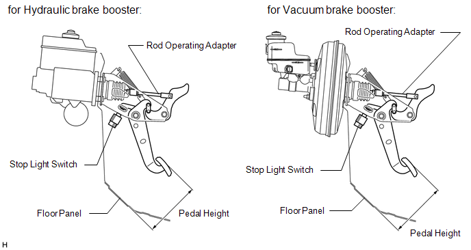
Pedal height from dash panel:
|
Type |
Pedal Height |
|---|---|
|
Automatic transmission |
164.4 to 174.4 mm (6.473 to 6.866 in.) |
|
Manual transmission |
160.5 to 170.5 mm (6.319 to 6.712 in.) |
NOTICE:
Do not adjust the pedal height. Doing so by changing the push rod length will structurally change the pedal ratio.
If the pedal height is incorrect, adjust the rod operating adapter length.
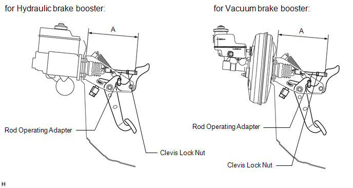
(b) Adjust the rod operating adapter length.
(1) Remove the clip and clevis pin.
(2) Loosen the clevis lock nut.
(3) Adjust the rod operating adapter length by turning the pedal push rod clevis.
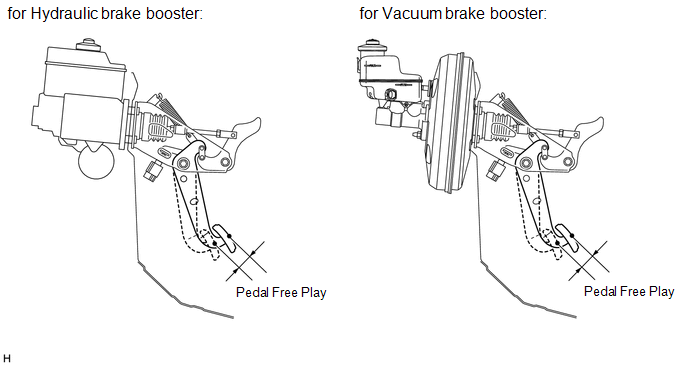
Rod operating adapter length A:
for Hydraulic brake booster
214 to 224 mm (8.425 to 8.818 in.)
for Vacuum brake booster
213 to 223 mm (8.386 to 8.780 in.)
(4) Tighten the clevis lock nut.
Torque:
26 N·m {260 kgf·cm, 19 ft·lbf}
(5) Install the clip and clevis pin.
- If the pedal height is incorrect even when the rod operating adapter is adjusted, check that there is no damage in the brake pedal, brake pedal lever, brake pedal bracket or dash panel.
- Even if there is damage, there is no problem if the reserve distance is within the standard value.
- If necessary, replace the parts.
2. INSPECT AND ADJUST STOP LIGHT SWITCH ASSEMBLY
HINT:
If the pedal height is incorrect, check and adjust the stop light switch.
(a) Disconnect the stop light switch connector from the stop light switch.
(b) Turn the stop light switch counterclockwise, and remove the stop light switch.
|
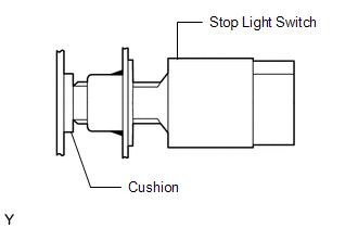
(c) Insert the stop light switch until the body comes into contact with the cushion. NOTICE:
|
|
|
(d) Make a quarter turn clockwise to install the stop light switch. NOTICE: The turning torque for installing the stop light switch: Torque: 1.5 N·m {15 kgf·cm, 13 in·lbf} or less |
|
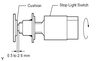
(e) Check the protrusion of the rod.
Protrusion of the rod:
0.5 to 2.6 mm (0.020 to 0.102 in.)
(f) Connect the stop light switch connector to the stop light switch.
3. INSPECT PEDAL FREE PLAY
(a) Stop the engine and depress the brake pedal several times until there is no more vacuum left in the booster.
(b) Push in the pedal until the beginning of the resistance is felt. Measure the distance as shown.
Pedal free play:
1 to 6 mm (0.04 to 0.24 in.)
4. INSPECT PEDAL RESERVE DISTANCE
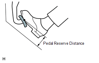
(a) Release the parking brake pedal.
With the engine running, depress the pedal and measure the pedal reserve distance as shown.
Pedal reserve distance from asphalt sheet at 490 N (50 kgf, 110.2 lbf):
More than 55 mm (2.17 in.)
If incorrect, troubleshoot the brake system.
 Components
COMPONENTS
ILLUSTRATION
...
 Removal
REMOVAL
PROCEDURE
1. PRECAUTION
NOTICE:
After turning the ignition switch off, waiting time may be required before disconnecting
the cable from the negative (-) battery terminal. Therefore, make ...
Other materials:
Installation
INSTALLATION
CAUTION / NOTICE / HINT
HINT:
Use the same procedure for both the RH and LH sides.
The procedure described below is for the LH side.
PROCEDURE
1. INSTALL FRONT SHOULDER BELT ANCHOR ADJUSTER ASSEMBLY
(a) Engage the guide to temporarily install the front ...
Installation
INSTALLATION
CAUTION / NOTICE / HINT
HINT:
Use the same procedure for the RH and LH sides.
The procedure described below is for the LH side.
PROCEDURE
1. REPAIR INSTRUCTION
(a) Clean the vehicle body surface.
(1) Using a heat light, heat the vehicle body surface.
Heating Te ...
Abbreviations Used In Manual
ABBREVIATIONS USED IN MANUAL
Abbreviations
Meaning
ABS
Anti-Lock Brake System
A/C
Air Conditioner
AC
Alternating Current
ACC
Accessory
ACIS
...
