Toyota Tacoma (2015-2018) Service Manual: Multi-terrain Select Indicator Light Remains ON
DESCRIPTION
Refer to Multi-terrain Select Indicator Light does not Come ON (See page
.gif) ).
).
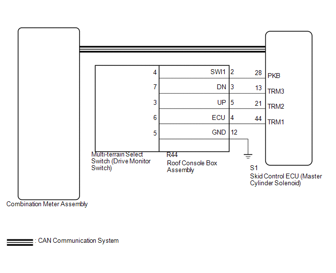
WIRING DIAGRAM
CAUTION / NOTICE / HINT
NOTICE:
- When replacing the skid control ECU (master cylinder solenoid), perform
calibration (See page
).
- Inspect the fuses for circuits related to this system before performing the following inspection procedure.
PROCEDURE
|
1. |
CHECK CAN COMMUNICATION SYSTEM |
| NG | .gif) |
GO TO CAN COMMUNICATION SYSTEM (HOW TO PROCEED WITH TROUBLESHOOTING) |
|
.gif)
|
2. |
CHECK DTC |
(a) Check for DTCs (See page
).
|
Result |
Proceed to |
|---|---|
|
DTC is not output |
A |
|
DTC is output |
B |
| B | |
REPAIR CIRCUITS INDICATED BY OUTPUT DTCS |
|
|
3. |
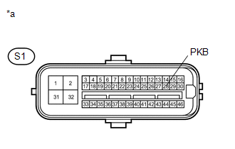
INSPECT SKID CONTROL ECU (PKB TERMINAL) |
(a) Disconnect the S1 skid control ECU (master cylinder solenoid) connector.
|
(b) Measure the resistance according to the value(s) in the table below. Standard Resistance:
|
|
(c) Reconnect the S1 skid control ECU (master cylinder solenoid) connector.
| NG | |
GO TO STEP 5 |
|
|
4. |
REPLACE COMBINATION METER ASSEMBLY |
(a) Replace the combination meter assembly a new one.
OK:
The multi-terrain select indicator light turns on or off in accordance with the switch operation.
| OK | |
REPLACE MASTER CYLINDER SOLENOID |
| NG | |
END |
|
5. |
INSPECT DRIVE MONITOR SWITCH |
(a) Remove the multi-terrain select switch (drive monitor switch) (See page
).
(b) Inspect the multi-terrain select (drive monitor switch) (See page
).
| NG | |
REPLACE DRIVE MONITOR SWITCH |
|
|
6. |
INSPECT ROOF CONSOLE BOX ASSEMBLY |
(a) Remove the roof console box assembly.
- for Double Cab: (See page
)
- for Access Cab: (See page
)
 Text in Illustration
|
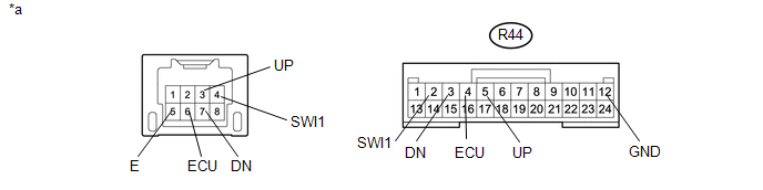
*a |
Component without harness connected (Roof Console Box Assembly) |
- |
- |
(b) Measure the resistance according the value(s) in the table below.
Standard Resistance:
|
Tester Connection |
Condition |
Specified Condition |
|---|---|---|
|
R44-2 (SWI1) - 4 |
Always |
Below 1 Ω |
|
R44-3 (DN) - 7 |
Always |
Below 1 Ω |
|
R44-4 (ECU) - 6 |
Always |
Below 1 Ω |
|
R44-5 (UP) - 3 |
Always |
Below 1 Ω |
|
R44-12 (GND) - 5 |
Always |
Below 1 Ω |
|
Result |
Proceed to |
|---|---|
|
OK |
A |
|
NG (for Double Cab) |
B |
|
NG (for Access Cab) |
C |
| A | |
REPAIR OR REPLACE HARNESS OR CONNECTOR (MASTER CYLINDER SOLENOID - ROOF CONSOLE BOX ASSEMBLY) |
| B | |
REPLACE ROOF CONSOLE BOX ASSEMBLY |
| C | |
REPLACE ROOF CONSOLE BOX ASSEMBLY |
 Multi-terrain Select Indicator Light does not Come ON
DESCRIPTION
When the transfer gear position is L4, the multi-terrain select indicator light
illuminates and control begins.
Under any of the following conditions, the multi-terrain select system d ...
 Brake Warning Light does not Come ON
DESCRIPTION
Refer to Brake Warning Light Remains ON (See page
).
WIRING DIAGRAM
Refer to Brake Warning Light Remains ON (See page
).
CAUTION / NOTICE / HINT
NOTICE:
When replacing th ...
Other materials:
New Key cannot be Registered
DESCRIPTION
If an electrical key transmitter could not be newly registered, wave interference
or a malfunction of the certification ECU (smart key ECU assembly), electrical key
transmitter sub-assembly, steering lock ECU (steering lock actuator or UPR bracket
assembly) or electrical key and T ...
LVDS Signal Malfunction (from Extension Module) (B1532,B156C)
DESCRIPTION
DTC Code
DTC Detection Condition
Trouble Area
B1532
When one of the conditions below is met:
Video signal (digital) is lost.
The stereo component tuner assembly is not connected while the
ignition swi ...
Destination Information Undefined (C1AB8)
DESCRIPTION
This DTC is stored when correct destination information is not sent from the
main body ECU (multiplex network body ECU) and destination information cannot be
confirmed after a blind spot monitor has been replaced.
DTC Code
DTC Detection Condition
Tr ...
