Toyota Tacoma (2015-2018) Service Manual: Microphone Circuit between Microphone and Radio Receiver
DESCRIPTION
The radio and display receiver assembly and telephone microphone assembly are connected to each other using the microphone connection detection signal lines.
Using this circuit, the radio and display receiver assembly sends power to the telephone microphone assembly, and the telephone microphone assembly sends microphone signals to the radio and display receiver assembly.
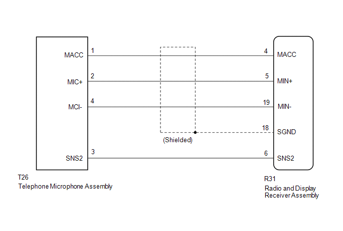
WIRING DIAGRAM
PROCEDURE
|
1. |
CHECK MICROPHONE |
|
(a) Enter the "Microphone Check" screen. Refer to Check Microphone in Operation Check. Click here |
|
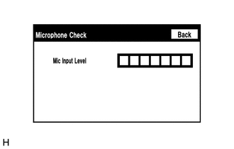
(b) When a voice is input into the microphone, check that the microphone input level meter changes according to the input voice.
OK:
Check result is normal.
| OK | .gif) |
PROCEED TO NEXT SUSPECTED AREA SHOWN IN PROBLEM SYMPTOMS TABLE |
|
.gif)
|
2. |
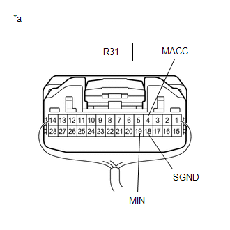
CHECK HARNESS AND CONNECTOR (RADIO AND DISPLAY RECEIVER ASSEMBLY - TELEPHONE MICROPHONE ASSEMBLY |
(a) Disconnect the R31 radio and display receiver assembly connector.
(b) Disconnect the T26 telephone microphone assembly connector.
(c) Measure the resistance according to the value(s) in the table below.
Standard Resistance:
|
Tester Connection |
Condition |
Specified Condition |
|---|---|---|
|
R31-4 (MACC) - T26-1 (MACC) |
Always |
Below 1 Ω |
|
R31-5 (MIN+) - T26-2 (MIC+) |
Always |
Below 1 Ω |
|
R31-19 (MIN-) - T26-4 (MIC-) |
Always |
Below 1 Ω |
|
R31-6 (SNS2) - T26-3 (SNS2) |
Always |
Below 1 Ω |
|
R31-4 (MACC) - Body ground |
Always |
10 kΩ or higher |
|
R31-5 (MIN+) - Body ground |
Always |
10 kΩ or higher |
|
R31-19 (MIN-) - Body ground |
Always |
10 kΩ or higher |
|
R31-18 (SGND) - Body ground |
Always |
10 kΩ or higher |
|
R31-6 (SNS2) - Body ground |
Always |
10 kΩ or higher |
(d) Reconnect the radio and display receiver assembly connector.
(e) Reconnect the telephone microphone assembly connector.
| NG | |
REPAIR OR REPLACE HARNESS OR CONNECTOR |
|
|
3. |
INSPECT RADIO AND DISPLAY RECEIVER ASSEMBLY |
(a) Remove the radio and display receiver assembly with connectors still connected.
|
(b) Measure the voltage according to the value(s) in the table below. Standard Voltage:
|
|
(c) Measure the resistance according to the value(s) in the table below.
Standard Resistance:
|
Tester Connection |
Condition |
Specified Condition |
|---|---|---|
|
R31-19 (MIN-) - Body ground |
Always |
Below 1 Ω |
|
R31-18 (SGND) - Body ground |
Always |
Below 1 Ω |
| NG | |
REPLACE RADIO AND DISPLAY RECEIVER ASSEMBLY |
|
|
4. |
INSPECT TELEPHONE MICROPHONE ASSEMBLY |
|
(a) Remove the telephone microphone assembly. Click here |
|
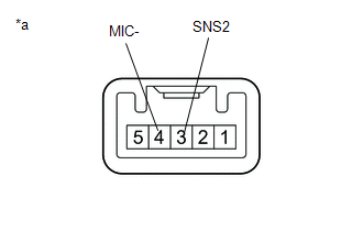
(b) Measure the resistance according to the value(s) in the table below.
Standard Resistance:
|
Tester Connection |
Condition |
Specified Condition |
|---|---|---|
|
3 (SNS2) - 4 (MIC-) |
Always |
Below 1 Ω |
(c) Install the telephone microphone assembly.
Click here .gif)
| NG | |
REPLACE TELEPHONE MICROPHONE ASSEMBLY |
|
|
5. |
INSPECT TELEPHONE MICROPHONE ASSEMBLY |
|
(a) Turn the ignition switch to ACC. |
|
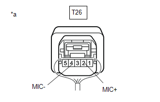
(b) Connect an oscilloscope to terminals 2 (MIC+) and 4 (MIC-) of the telephone microphone assembly connector.
(c) Check the waveform of the telephone microphone assembly using the oscilloscope.
Result|
Result |
Proceed to |
|---|---|
|
A waveform synchronized with the voice input to the amplifier microphone assembly is output |
A |
|
A waveform synchronized with the voice input to the amplifier microphone assembly is not output |
B |
| A | |
PROCEED TO NEXT SUSPECTED AREA SHOWN IN PROBLEM SYMPTOMS TABLE |
| B | |
REPLACE TELEPHONE MICROPHONE ASSEMBLY |
 Data Signal Circuit between Radio Receiver and Extension Module
DESCRIPTION
The stereo component tuner assembly sends the image data signal to the radio
and display receiver assembly via this circuit.
WIRING DIAGRAM
PROCEDURE
1.
CHEC ...
 Radio Receiver Power Source Circuit
DESCRIPTION
This is the power source circuit to operate the radio and display receiver assembly.
WIRING DIAGRAM
CAUTION / NOTICE / HINT
NOTICE:
Inspect the fuses for circuits related to ...
Other materials:
Air Inlet Control Servo Motor
Inspection
INSPECTION
PROCEDURE
1. INSPECT AIR INLET CONTROL SERVO MOTOR
(a) Inspect the servo motor operation.
(1) Connect the positive (+) lead from the battery to terminal 1 (FRS)
and negative (-) lead to terminals 2 (REC), then check that the shaft rotates
clockwise s ...
On-vehicle Inspection
ON-VEHICLE INSPECTION
PROCEDURE
1. INSPECT DRIVE BELT
(a) Visually check the belt for defects, such as excessive wear and frayed cords.
If any defects are found, replace the drive belt.
HINT:
Replace the belt if there are any missing ribs.
2. BLEED POWER STEERING SYSTEM
(a) Check the fluid ...
Short in Torque Converter Clutch Solenoid Circuit (Shift Solenoid Valve SL)
(P2769,P2770)
DESCRIPTION
Shift solenoid valve SL is turned on and off by signals from the ECM to control
the hydraulic pressure acting on the lock-up relay valve, which then controls operation
of the lock-up clutch.
DTC No.
DTC Detection Condition
Trouble Area
...
