Toyota Tacoma (2015-2018) Service Manual: Meter Illumination is Always Dark
DESCRIPTION
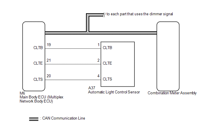
In this circuit, the combination meter assembly receives auto dimmer signals from the main body ECU (multiplex network body ECU) using the CAN communication system (CAN V1 Bus). When the meter CPU receives an auto dimmer signal, it dims the meter illumination (warning and indicator lights). The main body ECU (multiplex network body ECU) determines whether it is daytime, twilight, or nighttime based on the waveform transmitted from the automatic light control sensor. If the main body ECU (multiplex network body ECU) determines that it is daytime, the ECU does not send an auto dimmer signal. Therefore, the meter illumination will not dim even if the driver accidentally turns the light control switch to the tail or head position in daytime.
HINT:
When the meter illumination is always dark, there may be a malfunction in the automatic light control sensor, main body ECU (multiplex network body ECU), CAN communication system, harness or connector, or combination meter assembly.
NOTICE:
- Recognition code registration is necessary when replacing the main body ECU (multiplex network body ECU).
- If the main body ECU (multiplex network body ECU) is replaced, refer
to Registration (See page
.gif) )*1
)*1
- *1: w/ Smart Key System
WIRING DIAGRAM
CAUTION / NOTICE / HINT
HINT:
- The meter illumination can be customized by pressing the turning the light control rheostat knob in the combination meter assembly.
- If the light control rheostat knob is turned fully clockwise and the light control switch is turned to the tail, head or AUTO position at night, the meter illumination goes off.
PROCEDURE
|
1. |
CHECK CAN COMMUNICATION SYSTEM |
(a) Check if a CAN communication DTC is output (See page
).
|
Result |
Proceed to |
|---|---|
|
CAN communication DTC is not output |
A |
|
CAN communication DTC is output |
B |
| B | .gif) |
GO TO CAN COMMUNICATION SYSTEM |
|
.gif)
|
2. |
CONFIRM DTC OUTPUT (LIGHT CONTROL SENSOR CIRCUIT) |
(a) Check if DTC B1244 is output (See page
).
|
Result |
Proceed to |
|---|---|
|
B1244 is not output |
A |
|
B1244 is output |
B |
| B | |
GO TO LIGHTING SYSTEM |
|
|
3. |
CHECK OPERATION (AUTOMATIC LIGHT CONTROL SYSTEM) |
(a) Turn the ignition switch to ON.
(b) Turn the light control switch to the AUTO position.
(c) Cover the automatic light control sensor.
(d) Check the taillights and low beam headlights.
OK:
The taillights and low beam headlights come on.
(e) Uncover the automatic light control sensor.
(f) Check the low beam headlights and taillights.
OK:
The low beam headlights and taillights go off.
Result|
Result |
Proceed to |
|---|---|
|
Automatic light control system operates normally |
A |
|
Automatic light control system does not operate normally |
B |
| B | |
CHECK LIGHTING SETTING |
|
|
4. |
REPLACE MAIN BODY ECU (MULTIPLEX NETWORK BODY ECU) |
(a) Replace the main body ECU (multiplex network body ECU) with a new or a normal
one (See page ).
OK:
The operation of the combination meter assembly returns to normal.
HINT:
The meter CPU controls the meter illumination based on an auto dimmer signal from the main body ECU (multiplex network body ECU). When the meter illumination is always dark (very dim), it may be due to the main body ECU (multiplex network body ECU) sending an auto dimmer signal to the meter CPU because of a malfunction in the main body ECU (multiplex network body ECU).
| OK | |
END (MAIN BODY ECU (MULTIPLEX NETWORK BODY ECU) WAS DEFECTIVE) |
| NG | |
REPLACE COMBINATION METER ASSEMBLY |
 Fuel Receiver Gauge Malfunction
DESCRIPTION
The meter CPU uses the fuel sender gauge assembly to determine the level of the
fuel in the fuel tank. The resistance of the fuel sender gauge will vary between
approximately 13.5 Ω ...
 Meter Illumination does not Dim at Night
DESCRIPTION
In this circuit, the combination meter assembly auto dimmer signals from the
main body ECU using the CAN communication system (CAN V1 Bus). When the combination
meter assembly an auto ...
Other materials:
Illumination for Panel Switch does not Come on with Tail Switch ON
PROCEDURE
1.
CHECK VEHICLE SIGNAL (OPERATION CHECK)
(a) Enter the "Vehicle Signal Check Mode" screen. Refer to Check Vehicle Signal
in Operation Check (See page ).
(b) Check that the display changes between ON and OFF according to the light
control ...
Brake Switch "B" Circuit Short to Battery (P070312)
DESCRIPTION
The purpose of this circuit is to prevent the engine from stalling while driving
in lock-up when the brakes are suddenly applied.
When the brake pedal is depressed, this switch sends a signal to the ECM. Then
the ECM cancels the operation of the lock-up clutch while braking is in p ...
Inspection
INSPECTION
PROCEDURE
1. INSPECT SHIFT SOLENOID VALVE SL1
(a) Measure the resistance according to the value(s) in the table below.
Text in Illustration
*a
Component without harness connected
(Shift Solenoid Valve SL1)
Standa ...
