Toyota Tacoma (2015-2018) Service Manual: Inspection
INSPECTION
PROCEDURE
1. INSPECT SHIFT SOLENOID VALVE SL1
|
(a) Measure the resistance according to the value(s) in the table below. Text in Illustration
Standard Resistance:
If the value is not as specified, replace the shift solenoid valve SL1. |
|
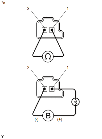
(b) Apply 12 V battery voltage to the shift solenoid valve and check that the valve moves and makes an operating noise.
OK:
|
Measurement Condition |
Specified Condition |
|---|---|
|
Valve moves and makes an operating noise |
If the operation cannot be done as specified, replace the shift solenoid valve SLT.
2. INSPECT SHIFT SOLENOID VALVE SL2
HINT:
Refer to Inspect Shift Solenoid Valve SL1.
3. INSPECT SHIFT SOLENOID VALVE SL3
HINT:
Refer to Inspect Shift Solenoid Valve SL1.
4. INSPECT SHIFT SOLENOID VALVE SL4
HINT:
Refer to Inspect Shift Solenoid Valve SL1.
5. INSPECT SHIFT SOLENOID VALVE SLU
HINT:
Refer to Inspect Shift Solenoid Valve SL1.
6. INSPECT SHIFT SOLENOID VALVE SLT
HINT:
Refer to Inspect Shift Solenoid Valve SL1.
7. INSPECT SHIFT SOLENOID VALVE SL
|
(a) Measure the resistance according to the value(s) in the table below. Text in Illustration
Standard Resistance:
If the value is not as specified, replace the shift solenoid valve SL. |
|
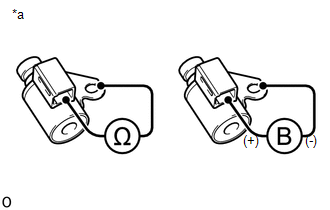
(b) Apply 12 V battery voltage to the shift solenoid valve and check that the valve moves and makes an operating noise.
OK:
|
Measurement Condition |
Specified Condition |
|---|---|
|
Valve moves and makes an operating noise |
 Removal
REMOVAL
PROCEDURE
1. DISCONNECT TRANSMISSION WIRE
(See page )
2. REMOVE VALVE BODY OIL STRAINER ASSEMBLY
(a) Remove the 3 bolts and valve body oil strainer assembly from the
trans ...
 Reassembly
REASSEMBLY
PROCEDURE
1. INSTALL SHIFT SOLENOID VALVE SLT
(a) Install the shift solenoid valve SLT and straight pin to the transmission
valve body assembly.
...
Other materials:
Freeze Frame Data
FREEZE FRAME DATA
1. FREEZE FRAME DATA
(a) Using the Techstream, check the vehicle condition (ECU, sensor) when the
brake system operates or a DTC is output.
2. CHECK FREEZE FRAME DATA WHEN BRAKE SYSTEM OPERATES
(a) Freeze frame data is stored when the brake system operates. The freeze frame
...
Dtc Check / Clear
DTC CHECK / CLEAR
NOTICE:
When the diagnosis system is changed from normal mode to check mode or vice versa,
all DTCs and freeze frame data recorded in normal mode are cleared. Before changing
modes, always check and make a note of DTCs and freeze frame data.
HINT:
DTCs which are sto ...
Adjustment
ADJUSTMENT
PROCEDURE
1. PREPARE VEHICLE FOR HEADLIGHT AIM ADJUSTMENT
(a) Prepare the vehicle:
Ensure that there is no damage or deformation to the body around the
headlights.
Fill the fuel tank.
Make sure that the oil is filled to the specified level.
Make sure that the co ...
