Toyota Tacoma (2015-2018) Service Manual: Installation
INSTALLATION
PROCEDURE
1. INSTALL RADIATOR ASSEMBLY
(a) Engage the 2 hooks and temporarily install the radiator assembly to the radiator support sub-assembly.
(b) Install the radiator assembly with the 4 bolts.
Torque:
18 N·m {184 kgf·cm, 13 ft·lbf}
2. INSTALL FAN SHROUD
(a) Install the fan pulley to the engine water pump assembly.
(b) Place the fan shroud together with the fan with fluid coupling between the radiator assembly and engine assembly.
NOTICE:
Be careful not to damage the radiator core.
|
(c) Align the paint marks on the heads of the water pump stud bolts with the paint marks of the same color on the outer edge of the fluid coupling flange and install the fan with fluid coupling to the engine water pump assembly. Text in Illustration
|
|
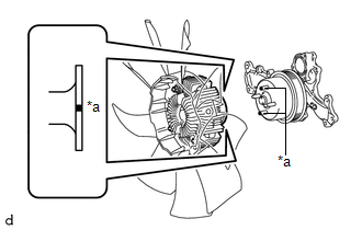
(d) Temporarily install the fan with fluid coupling to the engine water pump assembly with the 4 nuts. Tighten the nuts as much as possible by hand.
|
(e) Engage the 2 guides of the fan shroud to the radiator assembly as shown in the illustration. |
|
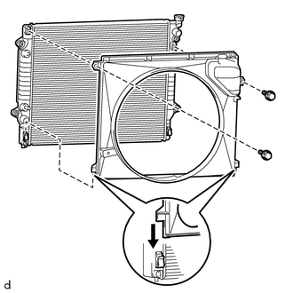
(f) Install the fan shroud to the radiator assembly with the 2 bolts.
Torque:
6.0 N·m {61 kgf·cm, 53 in·lbf}
(g) Install the fan and generator V belt (See page
.gif) ).
).
(h) Tighten the 4 nuts of the fan with fluid coupling.
Torque:
21 N·m {214 kgf·cm, 15 ft·lbf}
3. CONNECT TRANSMISSION OIL COOLER HOSE (for Automatic Transmission)
(a) w/o Air Cooled Transmission Oil Cooler:
|
(1) Connect the 2 transmission oil cooler hoses to the radiator assembly and slide the 2 hose clips to secure them. |
|
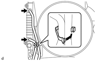
(2) Engage the clamp to install the 2 transmission oil cooler hoses to the fan shroud.
(b) w/ Air Cooled Transmission Oil Cooler:
|
(1) Connect the 2 transmission oil cooler hoses to the radiator assembly and slide the 2 hose clips to secure them. |
|
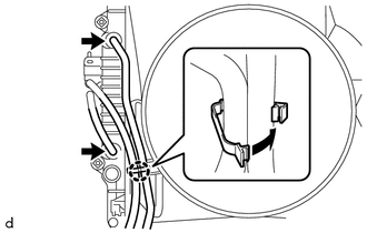
(2) Engage the clamp to install the 2 transmission oil cooler hoses to the fan shroud.
4. CONNECT RADIATOR RESERVE TANK HOSE
(a) Connect the radiator reserve tank hose to the radiator assembly.
5. INSTALL NO. 2 RADIATOR HOSE
|
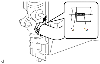
(a) Install the No. 2 radiator hose to the radiator assembly and slide the hose clip to secure it. Text in Illustration
NOTICE: Connect the No. 2 radiator hose so that the paint mark on the No. 2 radiator hose is aligned with the protrusion of the radiator assembly as shown in the illustration. |
|
|
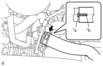
(b) Connect the No. 2 radiator hose to the water inlet with thermostat sub-assembly and slide the hose clip to secure it. Text in Illustration
NOTICE: Connect the No. 2 radiator hose so that the paint mark on the No. 2 radiator hose is aligned with the protrusion of the water inlet with thermostat sub-assembly as shown in the illustration. |
|
6. INSTALL NO. 1 RADIATOR HOSE
|
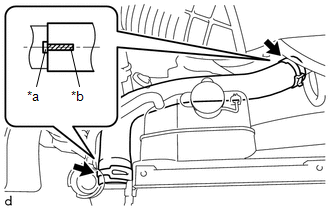
(a) Install the No. 1 radiator hose to the water outlet and radiator assembly and slide the 2 hose clips to secure it. Text in Illustration
NOTICE: Connect the No. 1 radiator hose so that the paint marks on the No. 1 radiator hose are aligned with the protrusions of the water outlet and radiator assembly as shown in the illustration. |
|
7. INSTALL RADIATOR SIDE DEFLECTOR LH
(a) Engage the 3 claws and install the radiator side deflector LH.
(b) Install the clip.
8. INSTALL RADIATOR SIDE DEFLECTOR RH
(a) Engage the 3 claws and install the radiator side deflector RH.
(b) Install the clip.
9. INSTALL RADIATOR SUPPORT TO FRAME SEAL
10. INSTALL V-BANK COVER SUB-ASSEMBLY
11. INSTALL RADIATOR GRILLE
(See page )
12. ADD ENGINE COOLANT
13. INSPECT FOR COOLANT LEAK
14. INSTALL NO. 1 ENGINE UNDER COVER SUB-ASSEMBLY
Torque:
30 N·m {306 kgf·cm, 22 ft·lbf}
15. INSTALL NO. 2 ENGINE UNDER COVER SUB-ASSEMBLY (w/ Off Road Package)
Torque:
30 N·m {306 kgf·cm, 22 ft·lbf}
 Inspection
INSPECTION
PROCEDURE
1. INSPECT RADIATOR CORE SUB-ASSEMBLY
Check the core plate for damage.
Text in Illustration
*1
Core Plate
*2
Radiator Core
...
 Reassembly
REASSEMBLY
PROCEDURE
1. INSTALL UPPER RADIATOR TANK
(a) Install a new upper radiator tank.
Text in Illustration
*1
Upper Radiator Tank
...
Other materials:
Test Mode Procedure
TEST MODE PROCEDURE
1. TEST MODE PROCEDURE (for Using Techstream)
HINT:
If the ignition switch is turned from the ON to the ACC or LOCK position
during test mode, DTCs related to the signal check function will be cleared.
During test mode, the skid control ECU (master cylinder ...
Disposal
DISPOSAL
CAUTION / NOTICE / HINT
CAUTION:
Before performing pre-disposal deployment of any SRS part, review and closely
follow all applicable environmental and hazardous material regulations. Pre-disposal
deployment may be considered hazardous material treatment.
PROCEDURE
1. PRECAUTION
...
No Sound can be Heard from Speakers
PROCEDURE
1.
CHECK AUDIO SETTINGS
(a) In sound output setting mode, set volume, fader and balance to the initial
values and check that the sound is normal.
OK:
Audio system returns to normal.
HINT:
Sound quality adjustment measures vary according to the type ...
