Toyota Tacoma (2015-2018) Service Manual: Installation
INSTALLATION
PROCEDURE
1. INSTALL REAR SEAT 3 POINT TYPE OUTER BELT ASSEMBLY
|
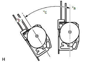
(a) Before installing the rear seat 3 point type outer belt assembly, check the ELR function. Text in Illustration
(1) When the inclination of the retractor is 15° or less, check that the belt can be pulled from the retractor. When the inclination of the retractor is over 45°, check that the belt locks. NOTICE: Do not disassemble the retractor. If operation is not as specified, replace the rear seat 3 point type outer belt assembly. |
|
|
(b) Engage the 2 guides to temporarily install the rear seat 3 point type outer belt assembly with the 2 bolts. |
|
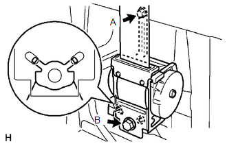
(c) Tighten bolt A, and then tighten bolt B.
Torque:
12.5 N·m {127 kgf·cm, 9 ft·lbf}
(for bolt A)
42 N·m {428 kgf·cm, 31 ft·lbf}
(for bolt B)
(d) Tighten the bolt to connect the shoulder anchor.
Torque:
42 N·m {428 kgf·cm, 31 ft·lbf}
(e) Check that the shoulder anchor rotates smoothly.
|
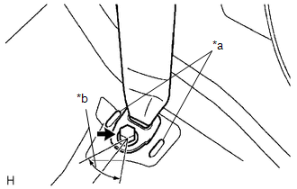
(f) Connect the floor anchor with the bolt. Text in Illustration
Torque: 42 N·m {428 kgf·cm, 31 ft·lbf} NOTICE:
|
|
(g) Check the ELR lock.
NOTICE:
The check should be performed with the rear seat 3 point type outer belt assembly installed.
(1) With the belt installed, check that the belt locks when it is pulled out quickly.
If the operation is not as specified, replace the rear seat 3 point type outer belt assembly.
(h) Remove the bolt to disconnect the floor anchor.
2. INSTALL QUARTER INSIDE TRIM BOARD
.gif)
3. CONNECT REAR SEAT 3 POINT TYPE OUTER BELT ASSEMBLY
4. INSTALL QUARTER TRIM LOWER PANEL
5. INSTALL LUGGAGE COMPARTMENT SIDE TRAY
6. CONNECT REAR DOOR OPENING TRIM WEATHERSTRIP
7. INSTALL REAR DOOR SCUFF PLATE
8. INSTALL REAR SEATBACK HINGE SUB-ASSEMBLY
9. INSTALL REAR SEATBACK ASSEMBLY
10. INSTALL REAR SEATBACK HINGE COVER
 Components
COMPONENTS
ILLUSTRATION
ILLUSTRATION
...
 Removal
REMOVAL
PROCEDURE
1. REMOVE REAR SEATBACK HINGE COVER
2. REMOVE REAR SEATBACK ASSEMBLY
3. REMOVE REAR SEATBACK HINGE SUB-ASSEMBLY
4. REMOVE REAR DOOR SCUFF PLATE
5. DISCONNECT REAR ...
Other materials:
Center Differential Lock Position Switch (C1282)
DESCRIPTION
DTC C1282 is stored only in test mode.
DTC Code
DTC Detection Condition
Trouble Area
C1282
Stored during test mode.
Harness or connector
Transfer system
Skid control ECU (master cylinder sole ...
Removal
REMOVAL
PROCEDURE
1. REMOVE NO. 2 ENGINE UNDER COVER SUB-ASSEMBLY (w/ Off Road Package)
2. REMOVE NO. 1 ENGINE UNDER COVER SUB-ASSEMBLY
3. DRAIN ENGINE COOLANT
4. REMOVE RADIATOR GRILLE
(See page )
5. REMOVE V-BANK COVER SUB-ASSEMBLY
6. REMOVE RADIATOR SUPPORT TO FRAME SEAL
7. R ...
Diameter of the Tire is not Uniform (C1337)
DESCRIPTION
The skid control ECU (brake actuator assembly) measures the speed of each wheel
by receiving signals from the speed sensors. These signals are used for recognizing
whether all 4 wheels are operating properly. Therefore, all wheel signals must indicate
the same speed.
D ...
