Toyota Tacoma (2015-2018) Service Manual: Installation
INSTALLATION
CAUTION / NOTICE / HINT
HINT:
- Use the same procedures for the RH side and LH side.
- The procedures listed below are for the LH side.
- When installing a roof drip side moulding clip, heat the vehicle body and clip using a heat light.
- When installing the moulding, heat the vehicle body and moulding using a heat light.
|
Item |
Temperature |
|---|---|
|
Vehicle Body |
40 to 60°C (104 to 140°F) |
|
Moulding |
20 to 30°C (68 to 86°F) |
|
Clip |
20 to 30°C (68 to 86°F) |
NOTICE:
Do not heat the vehicle body, moulding and roof drip side moulding clip excessively.
PROCEDURE
1. INSTALL ROOF DRIP SIDE FINISH MOULDING CLIP
HINT:
Perform this procedure only when installing new roof drip side moulding clips.
(a) Using a heat light, heat the roof drip side moulding clip installation areas on the vehicle body.
(b) Remove the double-sided tape from the vehicle body.
(c) Wipe off any tape adhesive residue with cleaner.
(d) Using a heat light, heat the roof drip side moulding clips.
(e) Remove the peeling paper from the face of the roof drip side moulding clips.
HINT:
After removing the peeling paper, keep the exposed adhesive free from foreign matter.
(f) Install the roof drip side moulding clips in the positions shown in the illustration.
HINT:
Press the clips firmly to install them.
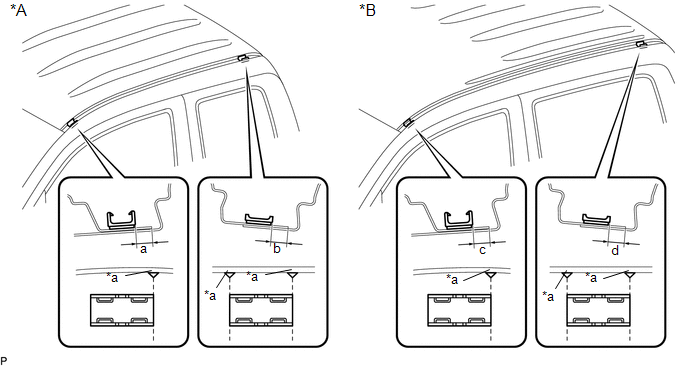 Text in Illustration
|
*A |
for Access Cab |
*B |
for Double Cab |
|
*a |
Alignment Mark |
- |
- |
|
Dimension |
Measurement |
Dimension |
Measurement |
|---|---|---|---|
|
a |
6.2 mm (0.244 in.) |
b |
5.8 mm (0.228 in.) |
|
c |
6.2 mm (0.244 in.) |
d |
5.8 mm (0.228 in.) |
2. INSTALL ROOF DRIP SIDE FINISH MOULDING
(a) for Double Cab:
(1) Clean the vehicle body surface.
- Using a heat light, heat the vehicle body surface.
- Remove the double-sided tape from the vehicle body.
- Wipe off any tape adhesive residue with cleaner.
(b) for Double Cab:
(1) Using a heat light, heat the vehicle body and a new roof drip side finish moulding.
(2) Remove the peeling paper from the face of the roof drip side finish moulding.
HINT:
After removing the peeling paper, keep the exposed adhesive free from foreign matter.
|
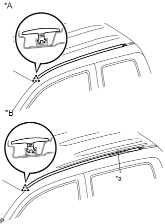
(c) Engage the clip to install the roof drip side finish moulding. Text in Illustration
HINT: Press the roof drip side finish moulding firmly to install it. |
|
3. INSTALL ROOF DRIP SIDE REAR FINISH MOULDING
(a) Clean the vehicle body surface.
(1) Using a heat light, heat the vehicle body surface.
(2) Remove the double-sided tape from the vehicle body.
(3) Wipe off any tape adhesive residue with cleaner.
(b) Install the moulding.
(1) Using a heat light, heat the vehicle body and a new roof drip side rear finish moulding.
(2) Remove the peeling paper from the face of the roof drip side rear finish moulding.
HINT:
After removing the peeling paper, keep the exposed adhesive free from foreign matter.
|
(3) Attach the clip to install the roof drip side rear finish moulding. Text in Illustration
HINT: Press the roof drip side rear finish moulding firmly to install it. |
|

 Removal
REMOVAL
CAUTION / NOTICE / HINT
HINT:
Use the same procedures for the RH side and LH side.
The procedures listed below are for the LH side.
When removing the moulding, heat the vehi ...
 Side Moulding
Components
COMPONENTS
ILLUSTRATION
ILLUSTRATION
Removal
REMOVAL
CAUTION / NOTICE / HINT
HINT:
Use the same procedure for the RH side and LH side.
The following procedure is ...
Other materials:
Precaution
PRECAUTION
IGNITION SWITCH EXPRESSIONS
(a) The type of ignition switch used on this model differs according to the specifications
of the vehicle. The expressions listed in the table below are used in this section.
Expression
Ignition Switch (Position)
Engine Swi ...
Brake Switch "B" Circuit Short to Battery (P070312)
DESCRIPTION
The purpose of this circuit is to prevent the engine from stalling while driving
in lock-up when the brakes are suddenly applied.
When the brake pedal is depressed, this switch sends a signal to the ECM. Then
the ECM cancels the operation of the lock-up clutch while braking is in p ...
Air Fuel Ratio Sensor
Components
COMPONENTS
ILLUSTRATION
Removal
REMOVAL
PROCEDURE
1. REMOVE AIR FUEL RATIO SENSOR (for Bank 1 Sensor 1)
(a) Disconnect the air fuel ratio sensor connector.
(b) Disengage the clamp to separate the air fuel ratio sensor wire ...
