Toyota Tacoma (2015-2018) Service Manual: Side Moulding
Components
COMPONENTS
ILLUSTRATION
ILLUSTRATION
Removal
REMOVAL
CAUTION / NOTICE / HINT
HINT:
- Use the same procedure for the RH side and LH side.
- The following procedure is for the LH side.
- When removing the lower No. 2 side panel moulding, heat the vehicle body and lower No. 2 side panel moulding using a heat light.
|
Item |
Temperature |
|---|---|
|
Vehicle Body |
40 to 60°C (104 to 140°F) |
|
Lower No. 2 Side Panel Moulding |
20 to 30°C (68 to 86°F) |
NOTICE:
Do not heat the vehicle body or lower No. 2 side panel moulding excessively.
PROCEDURE
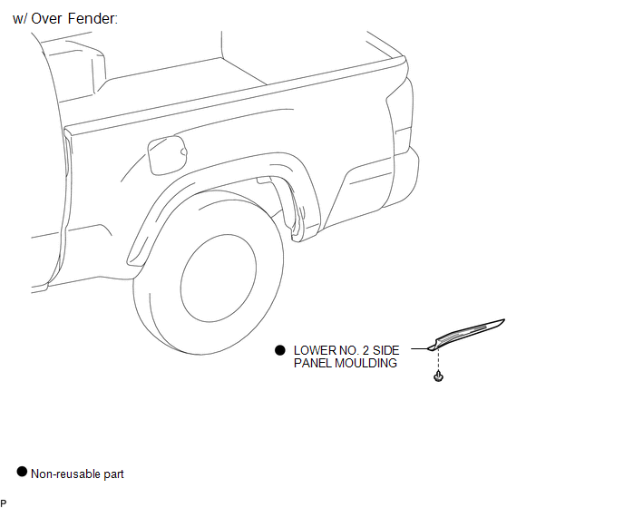
1. REMOVE LOWER NO. 2 SIDE PANEL MOULDING (w/ Over Fender)
(a) Using a heat light, heat the lower No. 2 side panel moulding.
|
(b) Remove the screw. Text in Illustration
|
|
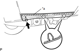
(c) Disengage the 2 claws, and peel off the double-sided tape to remove the lower No. 2 side panel moulding.
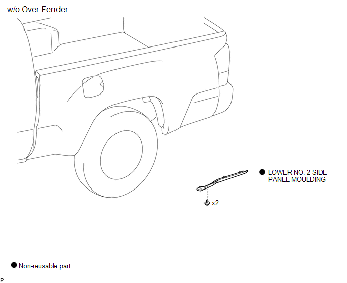
2. REMOVE LOWER NO. 2 SIDE PANEL MOULDING (w/o Over Fender)
(a) Using a heat light, heat the lower No. 2 side panel moulding.
|
(b) Remove the 2 screws. Text in Illustration
|
|
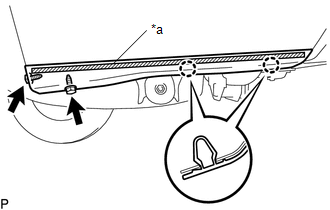
(c) Disengage the 2 claws, and peel off the double-sided tape to remove the lower No. 2 side panel moulding.
Installation
INSTALLATION
CAUTION / NOTICE / HINT
HINT:
- Use the same procedure for the RH side and LH side.
- The following procedure is for the LH side.
- When installing the lower No. 2 side panel moulding, heat the vehicle body and lower No. 2 side panel moulding using a heat light.
PROCEDURE
1. INSTALL LOWER NO. 2 SIDE PANEL MOULDING (w/ Over Fender)
(a) Clean the vehicle body surface.
(1) Using a heat light, heat the vehicle body surface.
(2) Remove the double-sided tape from the vehicle body.
(3) Clean off any tape adhesive residue with cleaner.
(b) Install a new lower No. 2 side panel moulding.
(1) Using a heat light, heat the vehicle body and a new lower No. 2 side panel moulding.
(2) Remove the release paper from the lower No. 2 side panel moulding.
HINT:
After removing the release paper, keep the exposed adhesive free from foreign matter.
|
(3) Engage the claws to install the lower No. 2 side panel moulding. Text in Illustration
|
|
.png)
(4) Install the screw.
2. INSTALL LOWER NO. 2 SIDE PANEL MOULDING (w/o Over Fender)
(a) Clean the vehicle body surface.
(1) Using a heat light, heat the vehicle body surface.
(2) Remove the double-sided tape from the vehicle body.
(3) Clean off any tape adhesive residue with cleaner.
(b) Install a new lower No. 2 side panel moulding.
(1) Using a heat light, heat the vehicle body and a new lower No. 2 side panel moulding.
(2) Remove the release paper from the lower No. 2 side panel moulding.
HINT:
After removing the release paper, keep the exposed adhesive free from foreign matter.
|
(3) Engage the claws to install the lower No. 2 side panel moulding. Text in Illustration
|
|
.png)
(4) Install the 2 screws.
 Installation
INSTALLATION
CAUTION / NOTICE / HINT
HINT:
Use the same procedures for the RH side and LH side.
The procedures listed below are for the LH side.
When installing a roof drip side mou ...
 Tail Gate Protector
Components
COMPONENTS
ILLUSTRATION
Removal
REMOVAL
PROCEDURE
1. REMOVE TAIL GATE PROTECTOR
(a) Using a T30 "TORX" socket wrench, remove the 8 screws.
...
Other materials:
On-vehicle Inspection
ON-VEHICLE INSPECTION
PROCEDURE
1. CHECK BATTERY CONDITION
NOTICE:
If the battery is weak or if the engine is difficult to start, recharge the battery
and perform inspections again before returning the vehicle to the customer.
(a) Check the battery for damage or deformation. If severe damage, ...
On-vehicle Inspection
ON-VEHICLE INSPECTION
PROCEDURE
1. CONNECT TECHSTREAM
(a) Warm up the engine.
(b) Turn the ignition switch to off.
(c) Connect the Techstream to the DLC3.
(d) Turn the ignition switch to ON.
(e) Turn the Techstream on.
(f) Enter the following menus: Chassis / ABS/VSC/TRAC / Active Test.
2. ...
Precaution
PRECAUTION
1. IGNITION SWITCH EXPRESSIONS
(a) The type of ignition switch used on this model differs depending on the specifications
of the vehicle. The expressions listed in the table below are used in this section.
Expression
Ignition Switch (Position)
Engine ...
