Toyota Tacoma (2015-2018) Service Manual: Installation
INSTALLATION
PROCEDURE
1. INSTALL REAR BUMPER ASSEMBLY
(a) Using an engine lifter or equivalent, engage the 2 pins to install the rear bumper assembly.
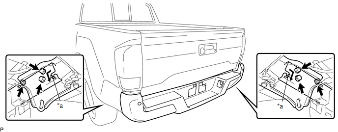 Text in Illustration
|
*a |
Pin |
- |
- |
NOTICE:
- Using plate lift attachments or equivalent, set the rear bumper assembly on a flat surface.
- Be sure to perform the operation with 2 persons or more.
- Be careful not to damage the rear bumper assembly.
(b) Install the 6 bolts.
Torque:
90 N·m {918 kgf·cm, 66 ft·lbf}
(c) Connect the 2 connectors.
2. PERFORM BLIND SPOT MONITOR BEAM AXIS INSPECTION (w/ Blind Spot Monitor)
Click here .gif)
3. PERFORM DIAGNOSTIC SYSTEM CHECK (w/ Blind Spot Monitor)
Click here
 Disassembly
DISASSEMBLY
PROCEDURE
1. REMOVE REAR BUMPER HOLE COVER
(a) Disengage the 2 clips to remove the rear bumper hole cover.
2. REMOVE REAR BUMPER PA ...
 Reassembly
REASSEMBLY
PROCEDURE
1. INSTALL REAR BUMPER SIDE STAY LH
(a) Install the rear bumper side stay LH with the 2 bolts.
Torque:
30 N·m {306 kgf·cm, 22 ft·lbf}
...
Other materials:
Terminals Of Ecu
TERMINALS OF ECU
1. CHECK MAIN BODY ECU (MULTIPLEX NETWORK BODY ECU) AND DRIVER SIDE JUNCTION
BLOCK
(a) Disconnect the main body ECU (multiplex network body ECU) connectors.
Text in Illustration
*1
Main Body ECU (Multiplex Network Body ECU)
-
-
...
Data List / Active Test
DATA LIST / ACTIVE TEST
1. DATA LIST
HINT:
Using the Techstream to read the Data List allows the values or states of switches,
sensors, actuators and other items to be read without removing any parts. This non-intrusive
inspection can be very useful because intermittent conditions or signals ...
Removal
REMOVAL
PROCEDURE
1. PRECAUTION
NOTICE:
After turning the ignition switch off, waiting time may be required before disconnecting
the cable from the negative (-) battery terminal.
Therefore, make sure to read the disconnecting the cable from the negative (-)
battery terminal notices before p ...
