Toyota Tacoma (2015-2018) Service Manual: Installation
INSTALLATION
PROCEDURE
1. INSTALL DIFFERENTIAL SIDE GEAR SHAFT OIL SEAL
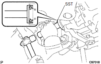
(a) Using SST and a hammer, install a new oil seal.
SST: 09554-30011
(b) Coat the oil seal lip with MP grease.
2. INSTALL FRONT DRIVE SHAFT ASSEMBLY LH
Click here .gif)
3. INSTALL FRONT DRIVE SHAFT ASSEMBLY RH
HINT:
Use the same procedure as for the LH side.
4. INSTALL FRONT SUSPENSION LOWER ARM LH
Click here
5. INSTALL FRONT SUSPENSION LOWER ARM RH
HINT:
Use the same procedure as for the LH side.
6. INSTALL TIE ROD END SUB-ASSEMBLY LH
Click here
7. INSTALL TIE ROD END SUB-ASSEMBLY RH
HINT:
Use the same procedure as for the LH side.
8. INSTALL FRONT SPEED SENSOR LH
Click here
9. INSTALL FRONT SPEED SENSOR RH
HINT:
Use the same procedure as for the LH side.
10. INSTALL FRONT STABILIZER LINK ASSEMBLY LH
Click here
11. INSTALL FRONT STABILIZER LINK ASSEMBLY RH
HINT:
Use the same procedure as for the LH side.
12. INSTALL FRONT AXLE SHAFT LH NUT
Click here
13. INSTALL FRONT AXLE SHAFT RH NUT
HINT:
Use the same procedure as for the LH side.
14. ADD DIFFERENTIAL OIL
Click here
15. INSPECT DIFFERENTIAL OIL
Click here
16. INSTALL NO. 1 ENGINE UNDER COVER SUB-ASSEMBLY
Torque:
30 N·m {306 kgf·cm, 22 ft·lbf}
17. INSTALL NO. 2 ENGINE UNDER COVER SUB-ASSEMBLY (w/ Engine Under Cover No, 2)
Torque:
30 N·m {306 kgf·cm, 22 ft·lbf}
18. INSTALL FRONT WHEELS
Torque:
113 N·m {1152 kgf·cm, 83 ft·lbf}
19. INSPECT AND ADJUST FRONT WHEEL ALIGNMENT
Click here
20. CONNECT CABLE TO NEGATIVE BATTERY TERMINAL
Torque:
5.4 N·m {55 kgf·cm, 48 in·lbf}
NOTICE:
When disconnecting the cable, some systems need to be initialized after the cable is reconnected.
Click here
21. CHECK VSC SENSOR SIGNAL (for Hydraulic Brake Booster)
Click here
22. CHECK VSC SENSOR SIGNAL (for Vacuum Brake Booster)
Click here
 Removal
REMOVAL
PROCEDURE
1. PRECAUTION
NOTICE:
After turning the ignition switch off, waiting time may be required before disconnecting
the cable from the negative (-) battery terminal. Therefore, make ...

Other materials:
Problem Symptoms Table
PROBLEM SYMPTOMS TABLE
HINT:
Use the table below to help determine the cause of problem symptoms. If multiple
suspected areas are listed, the potential causes of the symptoms are listed in order
of probability in the "Suspected Area" column of the table. Check each symptom by
check ...
Pattern Select Switch
Components
COMPONENTS
ILLUSTRATION
Removal
REMOVAL
PROCEDURE
1. REMOVE INSTRUMENT PANEL LOWER CENTER FINISH PANEL
(See page )
2. REMOVE PATTERN SELECT SWITCH ASSEMBLY
(a) Detach the 2 claws to remove the pattern select switch assembly from
the instrument panel lower c ...
Customize Parameters
CUSTOMIZE PARAMETERS
PROCEDURE
1. CUSTOMIZE WIRELESS DOOR LOCK CONTROL SYSTEM (w/ Smart Key System)
HINT:
The following items can be customized.
NOTICE:
When the customer requests a change in a function, first make sure that
the function can be customized.
Be sure to make a not ...
