Toyota Tacoma (2015-2018) Service Manual: Inspection
INSPECTION
PROCEDURE
1. INSPECT OIL PUMP RELIEF VALVE
|
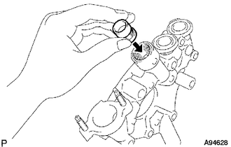
(a) Coat the oil pump relief valve with engine oil and check that it falls smoothly into the valve hole by its own weight. If the valve does not fall smoothly, replace the timing chain cover assembly. |
|
2. INSPECT OIL PUMP ROTOR SET
|
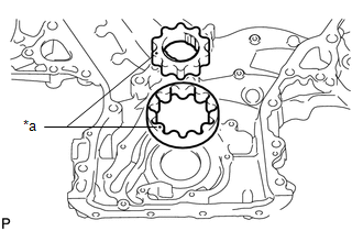
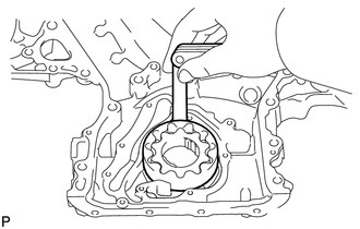
(a) Place the drive and driven rotors into the timing chain cover with the marks facing upward. Text in Illustration
|
|
(b) Check the rotor tip clearance.
|
(1) Using a feeler gauge, measure the clearance between the drive and driven rotor tips. Standard tip clearance: 0.06 to 0.16 mm (0.00236 to 0.00630 in.) Maximum tip clearance: 0.16 mm (0.00630 in.) If the clearance is more than the maximum, replace the drive and driven rotors as a set. |
|
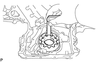
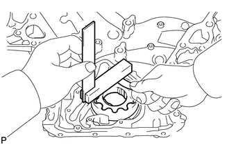
(c) Check the rotor side clearance.
|
(1) Using a feeler gauge and steel square, measure the clearance between the rotors and precision straightedge. Standard side clearance: 0.030 to 0.075 mm (0.00118 to 0.00295 in.) Maximum side clearance: 0.075 mm (0.00295 in.) If the clearance is more than the maximum, replace the drive and driven rotors as a set. If necessary, replace the timing chain cover assembly. |
|
(d) Check the rotor body clearance.
|
(1) Using a feeler gauge, measure the clearance between the driven rotor and body. Standard body clearance: 0.250 to 0.325 mm (0.00984 to 0.0128 in.) Maximum body clearance: 0.325 mm (0.0128 in.) If the clearance is more than the maximum, replace the drive and driven rotors as a set. If necessary, replace the timing chain cover assembly. |
|
 Disassembly
DISASSEMBLY
PROCEDURE
1. REMOVE OIL PUMP RELIEF VALVE
(a) Using a 27 mm socket wrench, remove the oil pump relief valve plug.
(b) Remove the oil pump relief valve spring and oil pump re ...
 Removal
REMOVAL
PROCEDURE
1. REMOVE ENGINE ASSEMBLY
(See page )
2. REMOVE IGNITION COIL ASSEMBLY
3. REMOVE ENGINE OIL LEVEL DIPSTICK GUIDE
4. REMOVE CAMSHAFT TIMING OIL CONTROL SOLENOID ASSEMBLY ...
Other materials:
Dtc Check / Clear
DTC CHECK / CLEAR
1. CHECK DTC (for TIRE PRESSURE WARNING ECU AND RECEIVER) (USING TECHSTREAM)
(a) Turn the ignition switch off.
(b) Connect the Techstream to the DLC3.
(c) Turn the ignition switch to ON.
(d) Turn the Techstream on.
(e) Enter the following menus: Chassis / Tire Pressure Monito ...
Front Radar Sensor (C1A10)
DESCRIPTION
C1A10 is output when there is an internal malfunction in the millimeter wave
radar sensor assembly.
DTC No.
Detection Item
DTC Detection Condition
Trouble Area
C1A10
Front Radar Sensor
While the vehicl ...
Parts Location
PARTS LOCATION
ILLUSTRATION
*A
for Double Cab
*B
for Access Cab
*C
w/ Back Door Power Window
-
-
*1
NO. 1 BACK PANEL PELAY
*2
NO. 2 BACK PANEL RELAY
...
