Toyota Tacoma (2015-2018) Service Manual: Inspection
INSPECTION
PROCEDURE
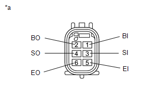
1. INSPECT NO. 1 ULTRASONIC SENSOR
|
(a) Measure the resistance according to the value(s) in the table below. Text in Illustration
Standard Resistance:
If the result is not as specified, replace the No. 1 ultrasonic sensor. |
|
 Components
COMPONENTS
ILLUSTRATION
ILLUSTRATION
...
 Removal
REMOVAL
PROCEDURE
1. REMOVE REAR BUMPER ASSEMBLY (w/ Towing Package)
(See page )
2. REMOVE REAR BUMPER ASSEMBLY (w/o Towing Package)
(See page )
3. REMOVE CONNECTOR COVER (w/ Towing Package) ...
Other materials:
Accelerator Pedal
Components
COMPONENTS
ILLUSTRATION
On-vehicle Inspection
ON-VEHICLE INSPECTION
PROCEDURE
1. INSPECT ACCELERATOR PEDAL SENSOR ASSEMBLY
(a) Connect the Techstream to the DLC3.
(b) Turn the ignition switch to ON.
(c) Turn the Techstream on.
(d) Enter the following menus: Powertrain / En ...
How To Proceed With Troubleshooting
CAUTION / NOTICE / HINT
HINT:
Use these procedures to troubleshoot the lighting system.
*: Use the Techstream.
PROCEDURE
1.
VEHICLE BROUGHT TO WORKSHOP
NEXT
2.
...
Precaution
PRECAUTION
1. DOOR CONTROL RECEIVER EXPRESSIONS
(a) The type of door control receiver used on this model differs according to
the specifications of the vehicle. The expressions listed in the table below are
used in this section.
Vehicle Specification
Part Name in Manual
...
