Toyota Tacoma (2015-2018) Service Manual: Inspection
INSPECTION
PROCEDURE
1. INSPECT FRONT NO. 1 SPEAKER ASSEMBLY (w/o Amplifier Box Speaker Assembly)
(a) Measure the resistance according to the value(s) in the table below.
Standard resistance:
|
Tester Connection |
Condition |
Specified Condition |
|---|---|---|
|
1 - 2 |
Always |
3.2 to 4.8 Ω |
If the result is not as specified, replace the front No. 1 speaker assembly.
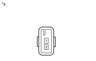
Text in Illustration|
*a |
Component without harness connected (Front No. 1 Speaker Assembly) |
2. INSPECT FRONT NO. 1 SPEAKER ASSEMBLY (w/ Amplifier Box Speaker Assembly)
(a) Measure the resistance according to the value(s) in the table below.
Standard resistance:
|
Tester Connection |
Condition |
Specified Condition |
|---|---|---|
|
1 - 2 |
Always |
1.4 to 2.2 Ω |
If the result is not as specified, replace the front No. 1 speaker assembly.
Text in Illustration|
*a |
Component without harness connected (Front No. 1 Speaker Assembly) |
 Removal
REMOVAL
CAUTION / NOTICE / HINT
HINT:
Use the same procedure for the RH and LH sides.
The procedure listed below is for the LH side.
PROCEDURE
1. REMOVE FRONT DOOR LOWER FRAME B ...
 Installation
INSTALLATION
CAUTION / NOTICE / HINT
HINT:
Use the same procedure for the RH and LH sides.
The procedure listed below is for the LH side.
PROCEDURE
1. INSTALL FRONT NO. 1 SPEAKE ...
Other materials:
Installation
INSTALLATION
CAUTION / NOTICE / HINT
CAUTION:
Some of these service operations affect the SRS airbag system. Read the precautionary
notices concerning the SRS airbag system before servicing (See page
).
HINT:
Use the same procedure for both the RH and LH sides.
The procedure des ...
Vehicle Speed Sensor "A" No Signal (P050031)
DESCRIPTION
The speed sensor detects the wheel speed and sends the appropriate signals to
the skid control ECU. The skid control ECU converts these wheel speed signals into
a pulse signal and outputs it to the ECM via the combination meter. The ECM determines
the vehicle speed based on the fr ...
Problem Symptoms Table
PROBLEM SYMPTOMS TABLE
HINT:
Use the table below to help determine the cause of problem symptoms.
If multiple suspected areas are listed, the potential causes of the symptom
are listed in order of probability in the "Suspected Area" column of the
table. Check each sym ...
