Toyota Tacoma (2015-2018) Service Manual: Inspection
INSPECTION
PROCEDURE
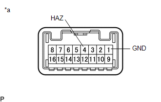
1. INSPECT HAZARD WARNING SIGNAL SWITCH ASSEMBLY (AIR CONDITIONING CONTROL ASSEMBLY)
(a) Check the resistance.
|
(1) Measure the resistance according to the value(s) in the table below. Text in Illustration
Standard Resistance:
If the result is not as specified, replace the hazard warning signal switch assembly (air conditioning control assembly). |
|
 Removal
REMOVAL
PROCEDURE
1. REMOVE FRONT DOOR SCUFF PLATE LH (for Double Cab)
2. REMOVE FRONT DOOR SCUFF PLATE LH (for Access Cab)
3. REMOVE COWL SIDE TRIM BOARD LH
4. REMOVE INSTRUMENT CLUS ...
 Installation
INSTALLATION
PROCEDURE
1. INSTALL HAZARD WARNING SIGNAL SWITCH ASSEMBLY (AIR CONDITIONING CONTROL ASSEMBLY)
(for Automatic Air Conditioning System)
(a) Connect the connectors.
(b) Engage the 8 c ...
Other materials:
VSC Buzzer Circuit
DESCRIPTION
The skid control ECU (master cylinder solenoid) is connected to the combination
meter via CAN communication.
The combination meter has a built-in VSC warning buzzer:
Sounds intermittently to inform the driver if the temperature of hydraulic
brake booster has increased exc ...
Lost Communication with ECM / PCM "A" (U0100,U0101,U0123,U0126,U0129,U0142,U0155)
DESCRIPTION
When a malfunction is detected between various ECUs and sensors, these DTCs are
stored.
DTC No.
Detection Item
DTC Detection Condition
Trouble Area
U0100
Lost Communication with ECM / PCM "A"
...
Front Evaporator Temperature Sensor
Inspection
INSPECTION
PROCEDURE
1. INSPECT COOLER THERMISTOR SENSOR
(a) Check the resistance.
(1) Measure the resistance and check the results in accordance with the
values in the table below.
Standard:
Tester Connection
Condition
...
