Toyota Tacoma (2015-2018) Service Manual: Immobiliser System does not Operate Properly
DESCRIPTION
The engine immobiliser system compares the ID code that is registered in the certification ECU (smart key ECU assembly) with the ID code of the transponder chip that is embedded in the electrical key transmitter sub-assembly.
WIRING DIAGRAM
(See page .gif) ).
).
CAUTION / NOTICE / HINT
CAUTION:
- The engine immobiliser system uses the LIN communication system. Inspect
the communication function by following How to Proceed with Troubleshooting.
Troubleshoot the engine immobiliser system after confirming that the communication
systems are functioning properly (See page
).
- Before replacing the ECM or certification ECU (smart key ECU assembly),
refer to Registration (See page ).
- After repair, confirm that no DTCs are output by performing "DTC Output Confirmation Operation".
HINT:
If an engine immobiliser system or SFI system DTC is output, first perform troubleshooting for the engine immobiliser system or SFI system DTC.
PROCEDURE
|
1. |
CHECK FOR DTC |
(a) Check for DTCs (See page ).
|
Result |
Proceed to |
|---|---|
|
DTCs are not output |
A |
|
DTCs are output |
B |
| B | .gif) |
GO TO DIAGNOSTIC TROUBLE CODE CHART |
|
.gif)
|
2. |
READ VALUE USING TECHSTREAM (IMMOBILISER FUEL CUT) |
(a) Connect the Techstream to the DLC3.
(b) Turn the engine switch on (IG).
(c) Turn the Techstream on.
(d) Enter the following menus: Powertrain / Engine / Data List.
(e) Read the Data List according to the display on the Techstream.
Engine|
Tester Display |
Measurement Item/Range |
Normal Condition |
Diagnostic Note |
|---|---|---|---|
|
Immobiliser Fuel Cut |
Status of immobiliser fuel cut / ON or OFF |
- |
- |
OK:
OFF is displayed after the engine is started.
Result|
Result |
Proceed to |
|---|---|
|
NG |
A |
|
OK |
B |
| B | |
GO TO SFI SYSTEM |
|
|
3. |
CHECK WHETHER ENGINE STARTS |
(a) Check that the engine starts 5 seconds after the engine switch turned on (IG).
OK:
Engine starts normally.
Result|
Result |
Proceed to |
|---|---|
|
NG |
A |
|
OK |
B |
| B | |
USE SIMULATION METHOD TO CHECK |
|
|
4. |
INSPECT ECM (TERMINAL IMI AND IMO) |
(a) Using an oscilloscope, check the waveform.
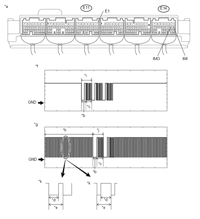 Text in Illustration
|
*a |
Component with harness connected (ECM) |
*b |
Approximately 160 ms |
|
*c |
Approximately 270 ms |
*d |
Approximately 40 ms |
|
*e |
Approximately 60 ms |
*f |
Waveform (IMO) |
|
*g |
Waveform (IMI) |
*h |
Waveform A |
|
*i |
Waveform B |
*j |
Waveform C |
|
*i |
Waveform A (detail) |
- |
- |
NOTICE:
The waveform shown in the illustration is an example for reference only. Noise, chattering, etc. are not shown.
Measurement Condition:
|
Tester Connection |
Condition |
Tool Setting |
Specified Condition |
|---|---|---|---|
|
E14-9 (IMO) - E11-1 (E1) |
Within 3 seconds of engine start or within 3 seconds of engine switch turned on (IG) after battery cable disconnected and reconnected |
2 V/DIV., 500 ms./DIV. |
Pulse generation (See waveform (IMO)) |
|
E14-8 (IMI) - E11-1 (E1) |
Within 3 seconds of engine start or within 3 seconds of engine switch turned on (IG) after battery cable disconnected and reconnected |
2 V/DIV., 500 ms./DIV. |
Pulse generation (See waveform (IMI)) |
|
Result |
Proceed to |
|---|---|
|
Normal waveform |
A |
|
Waveform A not output, or has abnormal wavelength or shape |
B |
|
Waveform B not output, or has abnormal wavelength or shape |
C |
|
Waveform C not output, or has abnormal wavelength or shape |
D |
| B | |
GO TO STEP 7 |
| C | |
REPLACE ECM |
| D | |
GO TO STEP 8 |
|
|
5. |
REGISTER ECU COMMUNICATION ID |
(a) Register the ECU communication ID (See page
).
|
|
6. |
CHECK WHETHER ENGINE STARTS |
(a) Check that the engine starts.
OK:
Engine starts normally.
| OK | |
END (COMMUNICATION ID REGISTRATION WAS DEFECTIVE) |
| NG | |
GO TO STEP 8 |
|
7. |
CHECK HARNESS AND CONNECTOR (CERTIFICATION ECU (SMART KEY ECU ASSEMBLY) - ECM) |
(a) Disconnect the C27 certification ECU (smart key ECU assembly) connector.
(b) Disconnect the E14 ECM connector.
(c) Measure the resistance according to the value(s) in the table below.
Standard Resistance:
|
Tester Connection |
Condition |
Specified Condition |
|---|---|---|
|
C27-7 (EFII) - E14-9 (IMO) |
Always |
Below 1 Ω |
|
C27-6 (EFIO) - E14-8 (IMI) |
Always |
Below 1 Ω |
|
C27-7 (EFII) or E14-9 (IMO) - Body ground |
Always |
10 kΩ or higher |
|
C27-6 (EFIO) or E14-8 (IMI) - Body ground |
Always |
10 kΩ or higher |
| NG | |
REPAIR OR REPLACE HARNESS OR CONNECTOR |
|
|
8. |
REPLACE CERTIFICATION ECU (SMART KEY ECU ASSEMBLY) |
(a) Replace the certification ECU (smart key ECU assembly) with a new one (See
page ).
|
|
9. |
REGISTER RECOGNITION CODE |
(a) Register the recognition codes in the ECUs (See page
).
|
|
10. |
REGISTER ECU COMMUNICATION ID |
(a) Register the ECU communication ID (See page
).
|
|
11. |
CHECK WHETHER ENGINE STARTS |
(a) Check that the engine starts.
OK:
Engine starts normally.
| OK | |
END (CERTIFICATION ECU (SMART KEY ECU ASSEMBLY) WAS DEFECTIVE) |
| NG | |
GO TO SFI SYSTEM |
 Security Indicator Light Does not Blink
DESCRIPTION
The certification ECU (smart key ECU assembly) blinks the security indicator
light when the immobiliser is set (engine switch off, or driver door is
opened and closed with ...

Other materials:
Installation of a mobile two-way radio system
The installation of a mobile two-way radio system in your vehicle could affect
electronic systems such as: ● Multiport fuel injection system/sequential multiport
fuel injection system
● Cruise control system
● Anti-lock brake system
● SRS airbag system
● Seat be ...
Output Speed Sensor Circuit No Signal (P0722,P077C,P077D)
DESCRIPTION
This sensor detects the rotation speed of the transmission output shaft and sends
signals to the ECM. By comparing the input turbine speed signal (NT) with the output
shaft speed sensor signal (SP2), the ECM detects the shift timing of the gears and
appropriately controls the engi ...
Transmitter ID1 Operation Stop (C2111/11-C2114/14)
DESCRIPTION
The tire pressure warning valve and transmitters that are installed in the tire
and wheel assemblies measure the tire pressure of each wheel. The measured values
are transmitted to the tire pressure warning ECU and receiver in the vehicle as
radio waves. The ECU compares the measu ...
