Toyota Tacoma (2015-2018) Service Manual: Front Fog Light Circuit
DESCRIPTION
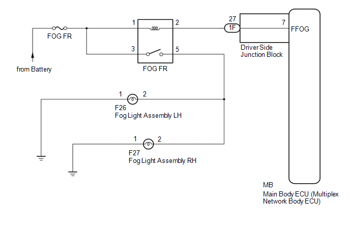
The main body ECU (multiplex network body ECU) controls the front fog lights.
WIRING DIAGRAM
CAUTION / NOTICE / HINT
NOTICE:
- Inspect the fuses for circuits related to this system before performing the following inspection procedure.
- If the main body ECU (multiplex network body ECU) is replaced, refer
to Registration (See page
.gif) ).*1
).*1
- *1: w/ Smart Key System
PROCEDURE
|
1. |
PERFORM ACTIVE TEST USING TECHSTREAM (FRONT FOG LIGHT RELAY) |
(a) Connect the Techstream to the DLC3.
(b) Turn the ignition switch to ON.
(c) Turn the Techstream on.
(d) Enter the following menus: Body Electrical / Main Body / Active Test.
(e) Perform the Active Test according to the display on the Techstream.
Main Body|
Tester Display |
Test Part |
Control Range |
Diagnostic Note |
|---|---|---|---|
|
Front Fog Light Relay |
Front Fog Light |
ON/OFF |
- |
OK:
Front fog lights illuminate.
| OK | .gif) |
PROCEED TO NEXT SUSPECTED AREA SHOWN IN PROBLEM SYMPTOMS TABLE |
|
.gif)
|
2. |
INSPECT FOG FR RELAY |
|
(a) Remove the FOG FR relay from the engine room relay block. |
|

(b) Measure the resistance according to the value(s) in the table below.
Standard Resistance:
|
Tester Connection |
Condition |
Specified Condition |
|---|---|---|
|
3 - 5 |
Battery voltage not applied to terminals 1 and 2 |
10 kΩ or higher |
|
3 - 5 |
Battery voltage applied to terminals 1 and 2 |
Below 1 Ω |
| NG | |
REPLACE FOG FR RELAY |
|
|
3. |
CHECK HARNESS AND CONNECTOR (BATTERY - FOG FR RELAY) |
(a) Measure the voltage according to the value(s) in the table below.
Standard Voltage:
|
Tester Connection |
Condition |
Specified Condition |
|---|---|---|
|
Relay terminal 1 - Body ground |
Always |
11 to 14 V |
|
Relay terminal 3 - Body ground |
Always |
11 to 14 V |
| NG | |
REPAIR OR REPLACE HARNESS OR CONNECTOR |
|
|
4. |
CHECK HARNESS AND CONNECTOR (FOG FR RELAY - DRIVER SIDE JUNCTION BLOCK) |
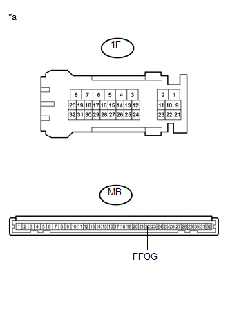
(a) Disconnect the 1F driver side junction block connector.
(b) Measure the resistance according to the value(s) in the table below.
Standard Resistance:
|
Tester Connection |
Condition |
Specified Condition |
|---|---|---|
|
Relay terminal 2 - 1F-27 |
Always |
Below 1 Ω |
|
1F-27 - Body ground |
Always |
10 kΩ or higher |
| NG | |
REPAIR OR REPLACE HARNESS OR CONNECTOR |
|
|
5. |
INSPECT DRIVER SIDE JUNCTION BLOCK |
|
(a) Remove the driver side junction block. |
|
(b) Measure the resistance according to the value(s) in the table below.
Standard Resistance:
|
Tester Connection |
Condition |
Specified Condition |
|---|---|---|
|
1F-27 - MB-7 (FFOG) |
Always |
Below 1 Ω |
|
1F-27 - Body ground |
Always |
10 kΩ or higher |
|
*a |
Component without harness connected (Driver Side Junction Block) |
| OK | |
REPLACE MAIN BODY ECU (MULTIPLEX NETWORK BODY ECU) |
| NG | |
REPLACE DRIVER SIDE JUNCTION BLOCK |
 Door Courtesy Switch Circuit
DESCRIPTION
The main body ECU (multiplex network Body ECU) receives a door open or closed
signal from each door courtesy light switch.
WIRING DIAGRAM
CAUTION / NOTICE / HINT
NOTICE:
R ...
 Hazard Warning Switch Circuit
DESCRIPTION
The combination meter assembly receives information signals from the telltale
light assembly (hazard warning signal switch).
WIRING DIAGRAM
CAUTION / NOTICE / HINT
NOTICE:
Inspect ...
Other materials:
Transmission Fluid Temperature Sensor "B" Circuit Short to Ground (P274011)
DESCRIPTION
The No. 2 ATF temperature sensor is installed in the transmission valve body
assembly.
If the ECM detects an abnormally high ATF temperature near this sensor, it illuminates
the warning indicator.
HINT:
The temperature of ATF easily rises when towing, climbing hills, in
...
Reassembly
REASSEMBLY
CAUTION / NOTICE / HINT
NOTICE:
When installing the hood bulge protector, heat the hood bulge surface
using the infrared light.
Do not heat the hood bulge excessively.
Item
Temperature
Hood Bulge
...
Sound Signal Circuit between Radio Receiver and Stereo Jack Adapter
DESCRIPTION
The No. 1 stereo jack adapter assembly sends the sound signal from an external
device to the navigation receiver assembly via this circuit.
If there is an open or short in the circuit, sound cannot be heard from the speakers
even if there is no malfunction in the stereo component a ...
