Toyota Tacoma (2015-2018) Service Manual: Front Floor Footrest
Components
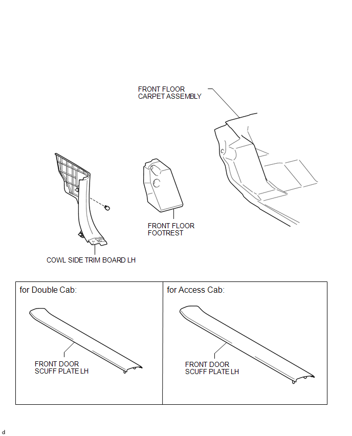
COMPONENTS
ILLUSTRATION
Installation
INSTALLATION
PROCEDURE
1. INSTALL FRONT FLOOR FOOTREST
|
(a) Engage the 2 clips to install the front floor footrest. |
|
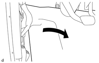
2. INSTALL FRONT FLOOR CARPET ASSEMBLY
|
(a) Return the front floor carpet assembly as shown in the illustration. |
|
3. INSTALL COWL SIDE TRIM BOARD LH
.gif)
4. INSTALL FRONT DOOR SCUFF PLATE LH (for Double Cab)
5. INSTALL FRONT DOOR SCUFF PLATE LH (for Access Cab)
Removal
REMOVAL
PROCEDURE
1. REMOVE FRONT DOOR SCUFF PLATE LH (for Double Cab)
.gif)
2. REMOVE FRONT DOOR SCUFF PLATE LH (for Access Cab)
3. REMOVE COWL SIDE TRIM BOARD LH
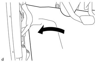
4. SEPARATE FRONT FLOOR CARPET ASSEMBLY
|
(a) Peel back the front floor carpet assembly as shown in the illustration. |
|
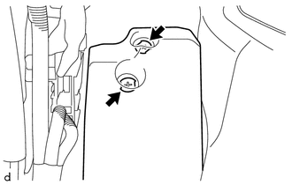
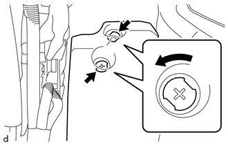
5. REMOVE FRONT FLOOR FOOTREST
|
(a) Rotate the 2 clips counterclockwise to remove the front floor footrest as shown in the illustration. |
|
 Reassembly
REASSEMBLY
PROCEDURE
1. INSTALL CONSOLE COMPARTMENT DOOR HINGE SUB-ASSEMBLY
(a) Engage the 2 guides to install the console compartment door hinge
sub-assembly.
...
 Rear Console Box
Components
COMPONENTS
ILLUSTRATION
ILLUSTRATION
Installation
INSTALLATION
PROCEDURE
1. INSTALL BOX BOTTOM MAT
(a) Engage the 10 guides and install the 2 box bottom mats.
2. INSTALL CO ...
Other materials:
Blind Spot Monitor Sensor Communication Stop Mode
DESCRIPTION
Detection Item
Symptom
Trouble Area
Blind Spot Monitor Sensor Communication Stop Mode
Either Condition is met:
Communication stop for "Blind Spot Monitor Master" is indicated
on the "Communic ...
Adjustment
ADJUSTMENT
PROCEDURE
1. PREPARE VEHICLE FOR HEADLIGHT AIM ADJUSTMENT
(a) Prepare the vehicle:
Ensure that there is no damage or deformation to the body around the
headlights.
Fill the fuel tank.
Make sure that the oil is filled to the specified level.
Make sure that the co ...
Fail-safe Chart
FAIL-SAFE CHART
1. FAIL-SAFE FUNCTION
(a) When communication fails in any of the CAN bus lines (communication lines),
a fail-safe function(s) will operate. The fail-safe function that is specified for
each system operates to prevent those systems from malfunctioning.
(b) The following table s ...
