Toyota Tacoma (2005–2015) Owners Manual: Floor mat
Use only floor mats designed specifically for vehicles of the same model and model year as your vehicle. Fix them securely in place onto the carpet.
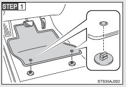
Insert the retaining hooks (clips) into the floor mat eyelets.
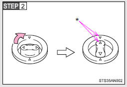
Turn the upper knob of each retaining hook (clip) to secure the floor mats in place.
*: Always align the  marks.
The shape of the retaining hooks (clips) may differ from that shown in the illustration.
CAUTION
Observe the following precautions.
Failure to do so may cause the driver’s floor mat to slip, possibly interfering with the pedals while driving. An unexpectedly high speed may result or it may become difficult to stop the vehicle, leading to a serious accident.
■When installing the driver‚Äôs floor mat
●Do not use floor mats designed for other models or different model year vehicles, even if they are Toyota Genuine floor mats.
●Only use floor mats designed for the driver‚Äôs seat.
●Always install the floor mat securely using the retaining hooks (clips) provided.
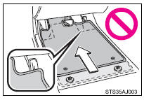
●Do not use two or more floor mats on top of each other.
●Do not place the floor mat bottom-side up or upside-down.
■Before driving
●Check that the floor mat is securely fixed in the correct place with all the provided retaining hooks (clips). Be especially careful to perform this check after cleaning the floor.
●With the engine stopped and the shift lever in P (automatic transmission) or N (manual transmission), fully depress each pedal to the floor to make sure it does not interfere with the floor mat.
 Seatback table
Front passenger’s seatback can be used as a temporary table only when the
vehicle is stopped.
Fold down the front passenger’s seat to use the seatback table.
CAUTION
■Caution while dr ...
 Luggage compartment features
Behind the rear seat (Double
Cab models only)
1.Cargo net hooks (vehicles with sub woofer)
2.Grocery bag hooks
3.Flashlight holder
4.Storage boxes
Deck
1. Auxiliary boxes
2. Tie-down cl ...
Other materials:
Status Signal Circuit
DESCRIPTION
This circuit sends a smart key system status signal from the certification ECU
(smart key ECU assembly) to the mobile wireless charger cradle assembly. Based on
this signal, the mobile wireless charger cradle assembly suspends or resumes wireless
charging.
WIRING DIAGRAM
CAUTI ...
Ambient Temperature Sensor Circuit (B1412)
DESCRIPTION
The ambient temperature sensor is installed in front of the condenser to detect
the ambient temperature which is used to control the air conditioning system AUTO
mode. This sensor is connected to the air conditioning amplifier assembly and detects
fluctuations in the ambient tempe ...
Radio Receiver Power Source Circuit
DESCRIPTION
This is the power source circuit to operate the navigation receiver assembly.
WIRING DIAGRAM
CAUTION / NOTICE / HINT
NOTICE:
Inspect the fuses for circuits related to this system before performing
the following inspection procedure.
PROCEDURE
1.
...
