Toyota Tacoma (2015-2018) Service Manual: Drive Belt
Components
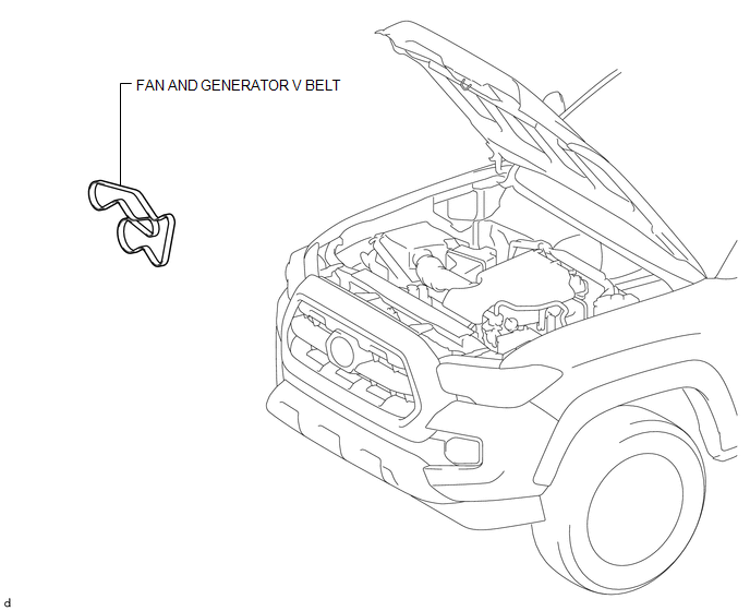
COMPONENTS
ILLUSTRATION
Precaution
PRECAUTION
NOTICE:
- Do not apply or add oil or grease to the belt tensioner to prevent abnormal noises from the belt tensioner pulley, belt squealing, etc.
- Do not allow oil or grease to adhere to the moving parts of the belt tensioner, as this may cause malfunctions.
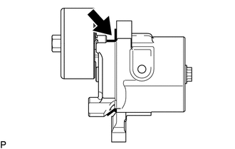
If oil or grease is on the location indicated by the arrow, replace the belt tensioner.
Installation
INSTALLATION
PROCEDURE
1. INSTALL FAN AND GENERATOR V BELT
|
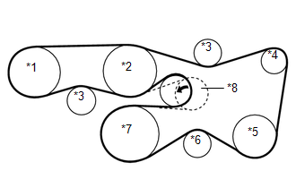
(a) Set the fan and generator V belt onto every part. Text in Illustration
|
|
(b) While turning the V-ribbed belt tensioner counterclockwise, remove the pin.
NOTICE:
Make sure that the fan and generator V belt is properly installed to each pulley.
(c) Check that the belt fits properly in the ribbed grooves.
HINT:
Make sure to check by hand that the belt has not slipped out of the grooves on the bottom of the pulley.
On-vehicle Inspection
ON-VEHICLE INSPECTION
PROCEDURE
1. INSPECT FAN AND GENERATOR V BELT
|
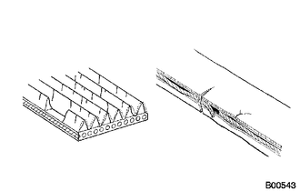
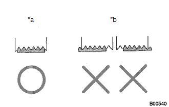
(a) Check the belt for wear, cracks or other signs of damage. If any of the following defects is found, replace the fan and generator V belt.
|
|
|
(b) Check that the belt fits properly in the ribbed grooves. Text in Illustration
HINT: Check with your hand to confirm that the belt has not slipped out of the grooves on the bottom of the pulley. If it has slipped out, replace the fan and generator V belt. Install a new fan and generator V belt correctly. |
|
2. INSPECT V-RIBBED BELT TENSIONER ASSEMBLY
(a) Check that nothing gets caught in the V-ribbed belt tensioner by turning it clockwise and counterclockwise.
If the result is not as specified, replace the V-ribbed belt tensioner.
Removal
REMOVAL
PROCEDURE
1. REMOVE FAN AND GENERATOR V BELT
|
(a) While turning the V-ribbed belt tensioner counterclockwise, align the service hole for the V-ribbed belt tensioner and the belt tensioner fixing position, and then insert a bar of 6 mm (0.236 in.) into the service hole to fix the V-ribbed belt tensioner in place. HINT: The pulley bolt for the V-ribbed belt tensioner has a left-hand thread. |
|
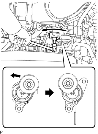
(b) Remove the fan and generator V belt.
 Removal
REMOVAL
PROCEDURE
1. REMOVE TIMING CHAIN COVER ASSEMBLY
(See page )
2. SEPARATE NO. 2 WATER BY-PASS PIPE (for Vacuum Brake Booster)
3. REMOVE VACUUM PUMP ASSEMBLY (for Vacuum Brake Booster)
...
 Engine Assembly
...
Other materials:
Fail-safe Chart
FAIL-SAFE CHART
1. FAIL-SAFE OPERATION AND DEACTIVATION CONDITION
TOUCH SELECT 2-4 AND HIGH-LOW SYSTEM
DTC No.
Fail-safe Operation
Fail-safe Deactivation Condition
U0100
Switching between H4 and L4 prohibited (shift position N*1 or neut ...
Certification Ecu
Components
COMPONENTS
ILLUSTRATION
Installation
INSTALLATION
PROCEDURE
1. INSTALL CERTIFICATION ECU (SMART KEY ECU ASSEMBLY)
(a) Install the certification ECU (smart key ECU assembly) with the 2 nuts.
Torque:
6.5 N·m {66 kgf·cm, 58 in·lbf}
(b) Engage the clamp to install the wire ...
Theft Deterrent System Presence Detection (B279C,B279C95)
DESCRIPTION
If an ECM that is incompatible with the engine immobiliser system is installed,
the ECM stores this DTC.
DTC No.
DTC Detection Condition
Trouble Area
DTC Output Confirmation Operation
B279C*1
An ECM that is incom ...
