Toyota Tacoma (2015-2018) Service Manual: Transfer L4 Position Switch Circuit (C1268)
DESCRIPTION
|
DTC No. |
Detection Item |
DTC Detection Condition |
Trouble Area |
|---|---|---|---|
|
C1268 |
Transfer L4 Position Switch Circuit |
Either of the following is detected:
|
|
HINT:
DTC will be output when conditions for either of the patterns in the table above are met.
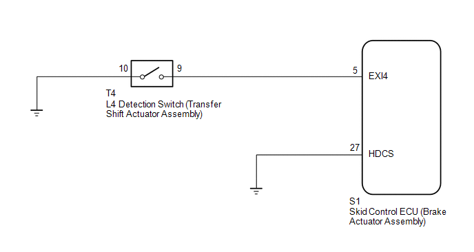
WIRING DIAGRAM
CAUTION / NOTICE / HINT
NOTICE:
When replacing the skid control ECU (brake actuator assembly), perform zero point
calibration and store system information (See page
.gif) ).
).
PROCEDURE
|
1. |
INSPECT L4 DETECTION SWITCH (TRANSFER SHIFT ACTUATOR ASSEMBLY) |
(a) Inspect the transfer shift actuator assembly (See page
).
OK:
The transfer shift actuator assembly is normal.
| NG | .gif) |
REPLACE TRANSFER SHIFT ACTUATOR ASSEMBLY |
|
.gif)
|
2. |
CHECK HARNESS AND CONNECTOR (BRAKE ACTUATOR ASSEMBLY - L4 DETECTION SWITCH) |
(a) Disconnect the S1 skid control ECU (brake actuator assembly) connector.
(b) Disconnect the T4 L4 detection switch (Transfer shift actuator assembly) connector.
(c) Measure the resistance according to the value(s) in the table below
Standard Resistance:
|
Tester Connection |
Condition |
Specified Condition |
|---|---|---|
|
S1-5 (EXI4) - T4-9 |
Always |
Below 1 Ω |
|
S1-5 (EXI4) - Body ground |
Always |
10 kΩ or higher |
|
T4-10 - Body ground |
Always |
Below 1 Ω |
| NG | |
REPAIR OR REPLACE HARNESS OR CONNECTOR (L4 DETECTION SWITCH CIRCUIT) |
|
|
3. |
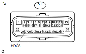
CHECK HARNESS AND CONNECTOR (HDCS TERMINAL) |
|
(a) Disconnect the skid control ECU (brake actuator assembly) connector. |
|
(b) Measure the resistance according to the value(s) in the table below.
Standard Resistance:
|
Tester Connection |
Condition |
Specified Condition |
|---|---|---|
|
S1-27 (HDCS) - Body ground |
Always |
Below 1 Ω |
|
*a |
Front view of wire harness connector (to Skid Control ECU (Brake Actuator Assembly)) |
| NG | |
REPAIR OR REPLACE HARNESS OR CONNECTOR |
|
|
4. |
RECONFIRM DTC |
(a) Clear the DTC (See page
).
(b) Check if the same DTC is recorded (See page
).
|
Result |
Proceed to |
|---|---|
|
DTC is output |
A |
|
DTC is not output |
B |
| A | |
REPLACE BRAKE ACTUATOR ASSEMBLY |
| B | |
USE SIMULATION METHOD TO CHECK |
 Vehicle Control History
VEHICLE CONTROL HISTORY
VEHICLE CONTROL HISTORY
(a) A part of the control history can be confirmed using the vehicle control
history.
Click here ...
 Steering Angle Sensor Zero Point Malfunction (C1290)
DESCRIPTION
The skid control ECU (brake actuator assembly) acquires steering angle sensor
zero point every time the ignition switch is turned ON and the vehicle is driven
at 35 km/h (22 mph) or m ...
Other materials:
Utility
UTILITY
NOTICE:
If the forward recognition camera has been replaced with a new one or
the windshield glass has been removed and installed, it is necessary to
perform Forward Recognition Camera Axis Adjustment. If the system is turned
on without performing Forward Recognition Ca ...
Automatic Disconnecting Differential Motor Control Circuit Open (P17A0)
DESCRIPTION
This DTC is output when an open circuit in the A.D.D. shift motor drive circuit
is detected.
DTC No.
Detection Item
DTC Detection Condition
Trouble Area
P17A0
Automatic Disconnecting Differential Motor Control Ci ...
Tires
Replace or rotate tires in accordance with maintenance schedules and treadwear.
■ Checking tire
1. New tread
2. Treadwear indicator
3. Worn tread
The location of treadwear indicators is shown by the “TWI” or “
” marks, etc., molded on the sidewall of each tire.
Check spare ti ...
