Toyota Tacoma (2015-2018) Service Manual: Disassembly
DISASSEMBLY
PROCEDURE
1. REMOVE STARTER YOKE ASSEMBLY
|
(a) Remove the nut and disconnect the lead wire from terminal C. |
|
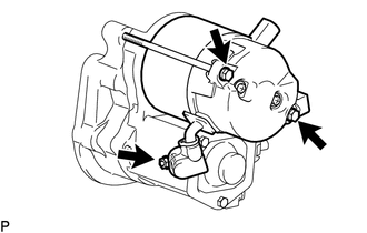
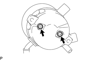
(b) Remove the 2 bolts.
(c) Pull out the starter yoke assembly and commutator end frame together with the starter armature assembly.
(d) Remove the O-ring from the starter yoke.
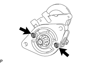
2. REMOVE MAGNET STARTER SWITCH ASSEMBLY
|
(a) Remove the 2 bolts and magnet starter switch assembly. |
|
|
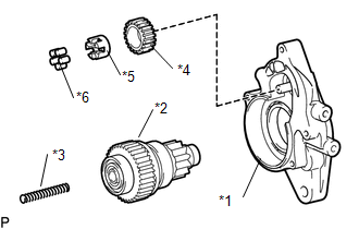
(b) Remove the idle gear, retainer, clutch roller, return spring and starter clutch sub-assembly from the starter drive housing assembly. Text in Illustration
|
|
|
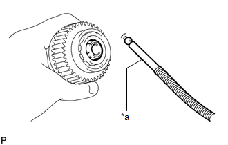
(c) Using a magnet hand, remove the steel ball from the starter clutch hole. Text in Illustration
|
|
3. REMOVE STARTER BRUSH HOLDER ASSEMBLY
|
(a) Remove the 2 screws and commutator end frame from the starter yoke assembly. NOTICE: While holding down the lead wire, remove the commutator end frame. |
|
(b) Remove the O-ring from the starter yoke assembly.
|
(c) Disconnect the 4 brushes from the starter brush holder assembly. (1) Using a screwdriver, hold back the brush spring. (2) Disconnect the brush from the starter brush holder assembly. |
|

(d) Remove the starter brush holder assembly.
4. REMOVE STARTER ARMATURE ASSEMBLY
(a) Remove the starter armature assembly from the starter yoke assembly.
 Components
COMPONENTS
ILLUSTRATION
ILLUSTRATION
...
 Inspection
INSPECTION
PROCEDURE
1. INSPECT MAGNET STARTER SWITCH ASSEMBLY
(a) Inspect the pull-in coil.
(1) Measure the resistance according to the value(s) in the table below.
Text in Illustra ...
Other materials:
Front Occupant Classification Sensor LH Circuit Malfunction (B1780)
DESCRIPTION
The occupant classification sensor front LH circuit consists of the occupant
detection ECU and the occupant classification sensor front LH.
DTC B1780 is set when a malfunction is detected in the occupant classification
sensor front LH circuit.
DTC No.
DTC Det ...
On-vehicle Inspection
ON-VEHICLE INSPECTION
PROCEDURE
1. INSPECT CAMSHAFT TIMING OIL CONTROL SOLENOID ASSEMBLY (for Intake Side)
(a) Connect the Techstream to the DLC3.
(b) Start the engine.
(c) Turn the Techstream on.
(d) Enter the following menus: Powertrain / Engine / Active Test / Control the
Intake VVT OCV D ...
Accelerator Pedal
Components
COMPONENTS
ILLUSTRATION
On-vehicle Inspection
ON-VEHICLE INSPECTION
PROCEDURE
1. INSPECT ACCELERATOR PEDAL SENSOR ASSEMBLY
(a) Connect the Techstream to the DLC3.
(b) Turn the ignition switch to ON.
(c) Turn the Techstream on.
(d) Enter the following menus: Powertrain / En ...
