Toyota Tacoma (2015-2018) Service Manual: Disassembly
DISASSEMBLY
PROCEDURE
1. REMOVE KNUCKLE GREASE RETAINER CAP (for 2WD)
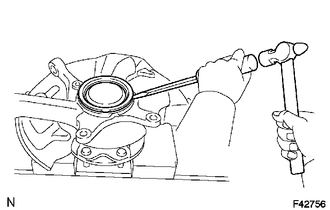
(a) Using a screwdriver and hammer, remove the knuckle grease retainer cap.
2. REMOVE FRONT AXLE HUB OIL SEAL (for 4WD)
(a) Using a screwdriver and hammer, remove the front axle hub oil seal.
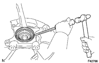
3. REMOVE FRONT WHEEL ADJUSTING NUT (for 2WD)
(a) Using SST and a hammer, unstake the front wheel adjusting nut.
SST: 09930-00010
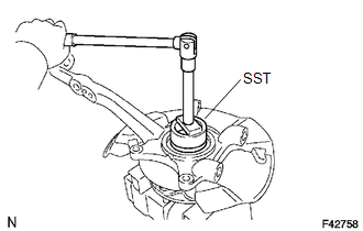
|
(b) Using SST, remove the front wheel adjusting nut. SST: 09318-12010 |
|
4. REMOVE FRONT AXLE HUB
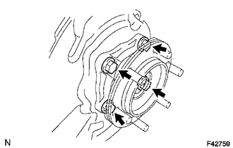
(a) Remove the 4 bolts and axle hub from the steering knuckle.
(b) Remove the O-ring from the axle hub.
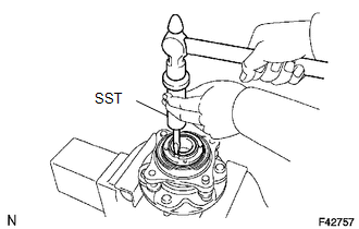
5. REMOVE FRONT AXLE WITH ABS ROTOR BEARING ASSEMBLY
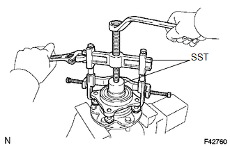
(a) Gently fix the front axle hub in a vise.
(b) Using SST, remove the bearing.
SST: 09710-30021
09710-03051
SST: 09950-40011
09951-04020
09952-04010
09953-04020
09954-04010
09955-04061
09957-04010
09958-04011
6. REMOVE FRONT AXLE HUB OIL SEAL
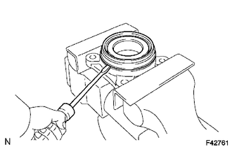
(a) Using a screwdriver, remove the front axle hub oil seal.
 Components
COMPONENTS
ILLUSTRATION
ILLUSTRATION
...
 Reassembly
REASSEMBLY
PROCEDURE
1. INSTALL FRONT AXLE HUB OIL SEAL
(a) Using a brass bar and a hammer, install a new front axle hub oil seal.
NOTICE:
Do not damage the oil seal.
2. INSTALL FRONT AXLE WIT ...
Other materials:
Components
COMPONENTS
ILLUSTRATION
HINT:
The following specifications are for BD20D (w/o Differential Lock). BD20D differentials
are equipped with M8 rear differential carrier to rear axel housing fasteners.
ILLUSTRATION
ILLUSTRATION
...
How To Proceed With Troubleshooting
CAUTION / NOTICE / HINT
Techstream can be used in steps 3, 6, 9 and 12.
PROCEDURE
1.
VEHICLE BROUGHT TO WORKSHOP
NEXT
2.
CUSTOMER PROBLEM ANALYSIS
...
Precaution
PRECAUTION
1. The type of ignition switch used on this model differs depending on the specifications
of the vehicle. The expressions listed in the table below are used in this section.
Expression
Ignition Switch (Position)
Engine Switch (Condition)
...
