Toyota Tacoma (2015-2018) Service Manual: Diagnosis System
DIAGNOSIS SYSTEM
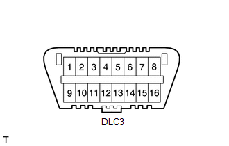
1. CHECK DLC3
(a) The vehicle's ECU uses the ISO 9141-2 for communication protocol. The terminal arrangement of the DLC3 complies with SAE J1962 and matches the ISO 15765-4 format.
|
Symbols (Terminal No.) |
Terminal Description |
Condition |
Specified Condition |
|---|---|---|---|
|
SIL (7) - SG (5) |
Bus + line |
During transmission |
Pulse generation |
|
CG (4) - Body ground |
Chassis ground |
Always |
Below 1 Ω |
|
BAT (16) - Body ground |
Battery positive |
Always |
11 to 14 V |
HINT:
If the display shows a communication error message when the Techstream is connected to the DLC3, the ignition switch is turned to ON and the Techstream is operated, there is a problem on the vehicle side or tool side.
- If communication is normal when the tool is connected to another vehicle, inspect the DLC3 on the original vehicle.
- If communication is still not possible when the tool is connected to another vehicle, the problem is probably in the tool itself. Consult the Service Department listed in the tool's instruction manual.
2. SYMPTOM SIMULATION
HINT:
The most difficult case in troubleshooting is when no symptoms occur. In such cases, a thorough customer problem analysis must be carried out. Then the same or similar conditions and environment in which the problem occurred in the customer's vehicle should be simulated. Regardless of the technician's experience or skill, if troubleshooting proceeds without confirmation of the problem symptoms, something important is likely to be overlooked and incorrect guesses may be made at some points in the repair operation.
This leads to a standstill in troubleshooting.
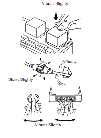
(a) Vibration method: When vibration seems to be the major cause.
HINT:
Perform the simulation method only during the primary check period (for approximately 6 seconds after the ignition switch is turned to on).
(1) Slightly vibrate the part of the sensor considered to be the cause of the problem with your fingers and check whether the malfunction occurs.
HINT:
Shaking the relays too strongly may result in open relays.
(2) Slightly shake the connector vertically and horizontally.
(3) Slightly shake the wire harness vertically and horizontally.
The connector joint and fulcrum of the vibration are the major areas to be checked thoroughly.
(b) Simulation method for DTC B1795: Turn the ignition switch from the lock to on, hold for 10 seconds, and then back to the lock position again 50 times in a row.
HINT:
DTC B1795 is output if the occupant detection ECU receives the ignition switch lock-on-lock signal 50 times in a row when a malfunction occurs in the power circuit for the occupant classification system.
3. FUNCTION OF PASSENGER AIRBAG ON/OFF INDICATOR
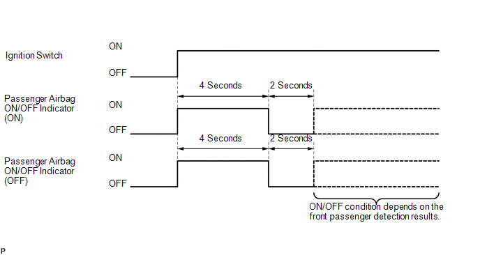
(a) Initial check
(1) Turn the ignition switch to on.
(2) The passenger airbag ON/OFF indicator (ON and OFF) comes on for approximately 4 seconds, then goes off for approximately 2 seconds.
(3) Approximately 6 seconds after the ignition switch is turned to on, the passenger airbag ON/OFF indicator will be ON/OFF depending on the conditions listed below.
|
Front Seat Passenger |
ON Indicator |
OFF Indicator |
SRS Warning Light |
|---|---|---|---|
|
Adult seated |
ON |
OFF |
OFF |
|
Child seated / Child restraint system set |
OFF |
ON |
OFF |
|
Vacant |
OFF |
OFF |
OFF |
|
Passenger occupant classification system failure |
OFF |
ON |
ON |
HINT:
- The passenger airbag ON/OFF indicator operates based on the timing chart
below in order to check the indicator light circuit.
- When the occupant classification system has trouble, both the SRS warning light and the passenger airbag ON/OFF indicator (OFF) come on. In this case, check the DTCs in the airbag system first.
4. PASSENGER AIRBAG ON/OFF INDICATOR CHECK
(a) Turn the ignition switch to on.
.png)
(b) Check that the passenger airbag ON/OFF indicator (ON and OFF) comes on for approximately 4 seconds, then goes off for approximately 2 seconds.
HINT:
Refer to the table in the previous step regarding the passenger airbag ON/OFF indicator when approximately 6 seconds have elapsed after the ignition switch is turned to on.
 System Diagram
SYSTEM DIAGRAM
...
 Dtc Check / Clear
DTC CHECK / CLEAR
1. DTC CHECK
HINT:
When DTC B1650/23 is detected as a result of troubleshooting for the
airbag system, troubleshoot the occupant classification system.
Use the Tec ...
Other materials:
Antenna Coil Open / Short (B2784)
DESCRIPTION
When an open or short circuit is detected in the antenna coil built into the
transponder key coil, the transponder key ECU assembly stores this DTC.
DTC No.
DTC Detection Condition
Trouble Area
DTC Output Confirmation Operation
...
Removal
REMOVAL
PROCEDURE
1. PRECAUTION
NOTICE:
After turning the ignition switch off, waiting time may be required before disconnecting
the cable from the negative (-) battery terminal. Therefore, make sure to read the
disconnecting the cable from the negative (-) battery terminal notices before pr ...
Diagnostic Trouble Code Chart
DIAGNOSTIC TROUBLE CODE CHART
Rear View Monitor System
DTC Code
Detection Item
See page
C1622
Open or Short Circuit in Back Camera Signal
...
