Toyota Tacoma (2015-2018) Service Manual: Compressor Lock Sensor Circuit (B1422)
SYSTEM DESCRIPTION
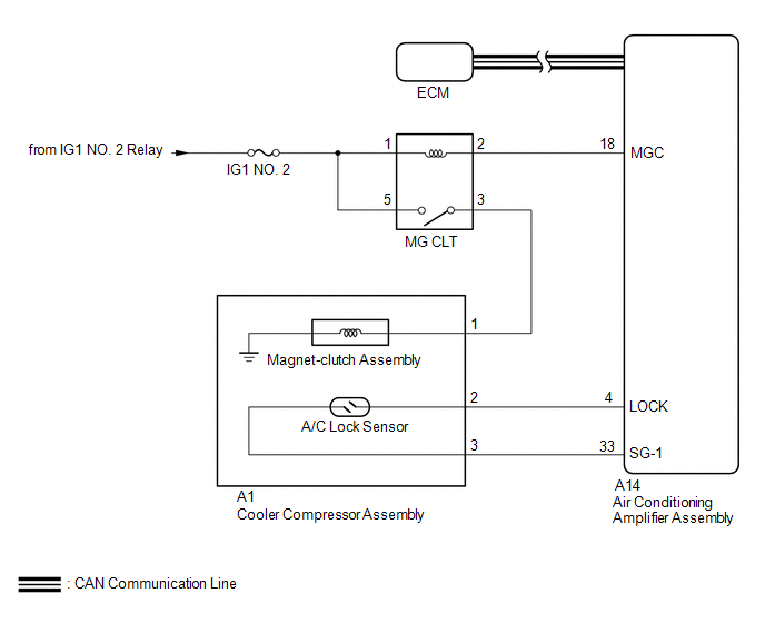
The ECM sends the engine speed signal to the air conditioning amplifier assembly via CAN communication.
The air conditioning amplifier assembly reads the difference between compressor speed and engine speed. When the difference becomes too large, the air conditioning amplifier assembly determines that the compressor is locked, and turns the magnet-clutch assembly off.
|
DTC No. |
DTC Detection Condition |
Trouble Area |
|---|---|---|
|
B1422 |
Open or short in A/C lock sensor circuit |
|
WIRING DIAGRAM
CAUTION / NOTICE / HINT
NOTICE:
- ECM malfunctions can affect the storage of this DTC. Therefore, check
all SFI system DTCs and confirm that the system is normal before performing
the following inspection.
- for 2TR-FE (See page
.gif) )
) - for 2GR-FKS (See page )
- for 2TR-FE (See page
- Inspect the fuses for circuits related to this system before performing the following procedure.
PROCEDURE
|
1. |
CHECK FOR DTC (CAN COMMUNICATION SYSTEM) |
(a) Use the Techstream to check if the CAN communication system is functioning normally.
Result|
Result |
Proceed to |
|---|---|
|
CAN DTC is not output |
A |
|
CAN DTC is output |
B |
| NG | .gif) |
GO TO CAN COMMUNICATION SYSTEM |
|
.gif)
|
2. |
INSPECT A/C LOCK SENSOR |
(a) Remove the A/C lock sensor (See page ).
(b) Inspect the A/C lock sensor (See page ).
| NG | |
REPLACE A/C LOCK SENSOR |
|
|
3. |
CHECK HARNESS AND CONNECTOR (AIR CONDITIONING AMPLIFIER ASSEMBLY - COOLER COMPRESSOR ASSEMBLY) |
(a) Disconnect the A1 cooler compressor assembly connector.
(b) Disconnect the A14 air conditioning amplifier assembly connector.
(c) Measure the resistance according to the value(s) in the table below.
Standard Resistance:
|
Tester Connection |
Condition |
Specified Condition |
|---|---|---|
|
A14-4 (LOCK) - A1-2 |
Always |
Below 1 Ω |
|
A14-33 (SG-1) - A1-3 |
Always |
Below 1 Ω |
|
A14-4 (LOCK) or A1-2 - Body ground |
Always |
10 kΩ or higher |
|
A14-33 (SG-1) or A1-3 - Body ground |
Always |
10 kΩ or higher |
|
Result |
Proceed to |
|---|---|
|
NG |
A |
|
OK (When troubleshooting according to Problem Symptoms Table) |
B |
|
OK (When troubleshooting according to the DTC) |
C |
| A | |
REPAIR OR REPLACE HARNESS OR CONNECTOR |
| B | |
PROCEED TO NEXT SUSPECTED AREA SHOWN IN PROBLEM SYMPTOMS TABLE |
| C | |
REPLACE AIR CONDITIONING AMPLIFIER ASSEMBLY |
 Evaporator Temperature Sensor Circuit (B1413)
DESCRIPTION
The cooler thermistor sensor (evaporator temperature sensor) is installed on
the evaporator in the air conditioner unit to detect the temperature of the cooled
air that has passed thr ...
 PTC Heater Circuit
DESCRIPTION
PTC HTR heater relays are closed in accordance with signals from the air conditioning
amplifier assembly and power is supplied to the quick heater assembly installed
on the radiator h ...
Other materials:
System Description
SYSTEM DESCRIPTION
1. GENERAL
This system has the following functions: manual slide open and close; auto slide
open and close; manual tilt up and down; auto tilt up and down; jam protection;
key off operation; key-linked open and close; wireless transmitter-linked open sliding
roof open warn ...
Reassembly
REASSEMBLY
CAUTION / NOTICE / HINT
HINT:
Use the same procedures for both the LH and RH sides.
The procedure described below is for the LH side.
PROCEDURE
1. INSTALL SIDE TURN SIGNAL LIGHT ASSEMBLY (w/ Side Turn Signal Light)
2. INSTALL OUTER MIRROR COVER (w/o Side Turn Si ...
Steering Angle Sensor Power Source Voltage Malfunction (C1432)
DESCRIPTION
The skid control ECU (brake actuator assembly) outputs this DTC when it receives
a sensor power source malfunction signal from the steering angle sensor.
DTC No.
Detection Item
DTC Detection Condition
Trouble Area
C1432
...
