Toyota Tacoma (2015-2018) Service Manual: Components
COMPONENTS
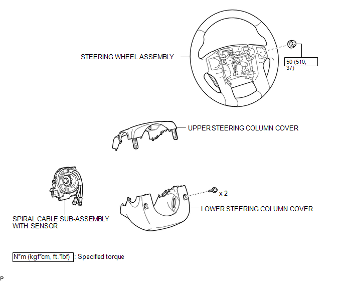
ILLUSTRATION

 Installation
INSTALLATION
PROCEDURE
1. INSTALL SPIRAL CABLE SUB-ASSEMBLY WITH SENSOR
(a) Check that the ignition switch is off.
(b) Check that the battery n ...
Other materials:
Driver Side Seat Heater does not Operate
DESCRIPTION
When the seat heater switch on the air conditioning control assembly is operated,
the air conditioning amplifier assembly receives the signal. The air conditioning
amplifier assembly receives the signal and operates the front seat heater.
WIRING DIAGRAM
CAUTION / NOTICE / HINT
...
Removal
REMOVAL
PROCEDURE
1. REMOVE REAR SEAT CUSHION ASSEMBLY
2. REMOVE NO. 4 ROOM PARTITION COVER LH
3. REMOVE NO. 4 ROOM PARTITION COVER RH
4. REMOVE NO. 3 ROOM PARTITION COVER
5. REMOVE BACK PANEL GARNISH HOLE PLUG
6. REMOVE BACK PANEL TRIM
7. REMOVE FRONT DOOR SCUFF PLATE ...
Multi-terrain Select Indicator Light does not Come ON
DESCRIPTION
When the transfer gear position is L4, the multi-terrain select indicator light
illuminates and control begins.
Under any of the following conditions, the multi-terrain select system does not
begin control and the multi-terrain select indicator light does not illuminate.
Th ...
