Toyota Tacoma (2015-2018) Service Manual: Components
COMPONENTS
ILLUSTRATION
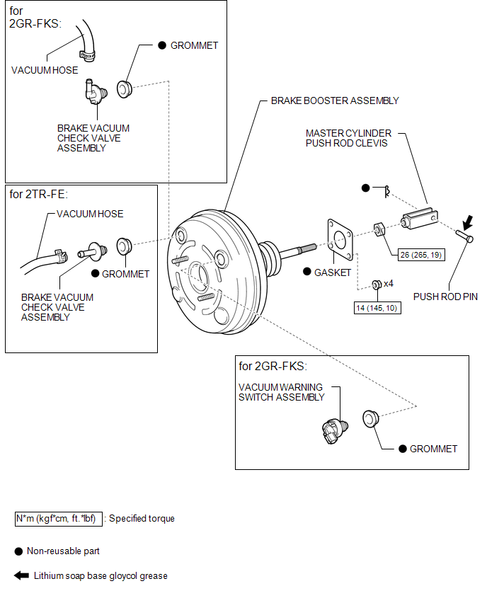
 Brake Booster
...
 On-vehicle Inspection
ON-VEHICLE INSPECTION
PROCEDURE
1. CHECK BRAKE BOOSTER ASSEMBLY
(a) Airtightness check.
Text in Illustration
*a
Correct
...
Other materials:
Blind Spot Monitor Main Switch
Components
COMPONENTS
ILLUSTRATION
Removal
REMOVAL
PROCEDURE
1. REMOVE INSTRUMENT PANEL LOWER CENTER FINISH PANEL
(See page )
2. REMOVE BLIND SPOT MONITOR MAIN SWITCH (WARNING CANCELING SWITCH ASSEMBLY)
(a) Disengage the 2 claws to remove the blind spot monitor main switch ...
Fail-safe Chart
FAIL-SAFE CHART
FAIL-SAFE FUNCTION
(a) When a malfunction occurs in the pre-collision system, a message will be
displayed on the multi-information display and the pre-collision system will be
disabled depending on the malfunction.
Warning Message
Cause
DTC No. ...
Air Outlet Control Servo Motor
Inspection
INSPECTION
PROCEDURE
1. INSPECT MODE CONTROL SERVO MOTOR
(a) Inspect the servo motor operation.
(1) When 12V is applied between terminals 4 (IGN) and 1 (GND), and 0V
is applied between terminals 2 (SIG) and 1 (GND), check that the line connecting
the 2 notches ...
