Toyota Tacoma (2015-2018) Service Manual: Air Outlet Control Servo Motor
Inspection
INSPECTION
PROCEDURE
1. INSPECT MODE CONTROL SERVO MOTOR
|
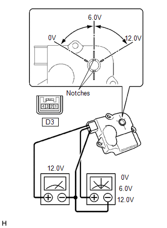
(a) Inspect the servo motor operation. (1) When 12V is applied between terminals 4 (IGN) and 1 (GND), and 0V is applied between terminals 2 (SIG) and 1 (GND), check that the line connecting the 2 notches moves to the 0V position. If the result is not as specified, replace the mode control servo motor. (2) When 12V is applied between terminals 4 (IGN) and 1 (GND), and 6V is applied between terminals 2 (SIG) and 1 (GND), check that the line connecting the 2 notches moves to the 6V position. If the result is not as specified, replace the mode control servo motor. (3) When 12V is applied between terminals 4 (IGN) and 1 (GND), and between terminals 2 (SIG) and 1 (GND), check that the line connecting the 2 notches moves to the 12V position. If the result is not as specified, replace the mode control servo motor. |
|
 Air Mix Control Servo Motor
Inspection
INSPECTION
PROCEDURE
1. INSPECT AIR MIX CONTROL SERVO MOTOR (for Manual Air Conditioning System)
(a) Inspect the servo motor operation.
Text in Illustration
...
 Ambient Temperature Sensor
Components
COMPONENTS
ILLUSTRATION
Inspection
INSPECTION
PROCEDURE
1. INSPECT AMBIENT TEMPERATURE SENSOR
(a) Measure the resistance according to the value(s) in the table below ...
Other materials:
Inspection
INSPECTION
PROCEDURE
1. INSPECT REAR AXLE SHAFT
(a) Using a dial indicator, measure the runout of the shaft and flange.
Maximum runout:
Shaft runout: 1.5 mm (0.0591 in.)
Flange runout: 0.05 mm (0.0020 in.)
If the rear axle shaft or flange is damaged or worn, or the runout is greater
than ...
Diagnostic Trouble Code Chart
DIAGNOSTIC TROUBLE CODE CHART
HINT:
If a trouble code is output during the DTC check, inspect the trouble areas listed
for that code. For details of the code, refer to the "See page".
DTC Code
Detection Item
See page
B1500
F ...
Automatic Transmission Unit(for 2gr-fks)
Components
COMPONENTS
ILLUSTRATION
ILLUSTRATION
ILLUSTRATION
ILLUSTRATION
ILLUSTRATION
ILLUSTRATION
ILLUSTRATION
ILLUSTRATION
ILLUSTRATION
...
