Toyota Tacoma (2015-2018) Service Manual: Installation
INSTALLATION
PROCEDURE
1. INSTALL REAR SEAT 3 POINT TYPE OUTER BELT ASSEMBLY
|
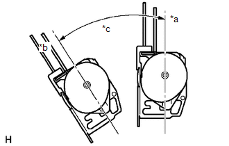
(a) Before installing the rear seat 3 point type outer belt assembly, check the ELR function. Text in Illustration
(1) When the inclination of the retractor is 15° or less, check that the belt can be pulled from the retractor. When the inclination of the retractor is over 45°, check that the belt locks. NOTICE: Do not disassemble the retractor. If operation is not as specified, replace the rear seat 3 point type outer belt assembly. |
|
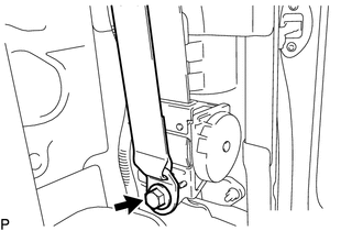
(b) Engage the 2 guides to install the rear seat 3 point type outer belt assembly with the bolt.
Torque:
12.5 N·m {127 kgf·cm, 9 ft·lbf}
(c) Tighten the bolt to connect the shoulder anchor.
Torque:
42 N·m {428 kgf·cm, 31 ft·lbf}
(d) Check that the shoulder anchor rotates smoothly.
|
(e) Connect the floor anchor with the bolt. Torque: 42 N·m {428 kgf·cm, 31 ft·lbf} |
|
(f) Check the ELR lock.
NOTICE:
The check should be performed with the rear seat 3 point type outer belt assembly installed.
(1) With the belt installed, check that the belt locks when it is pulled out quickly.
If the operation is not as specified, replace the rear seat 3 point type outer belt assembly.
(g) Remove the bolt to disconnect the floor anchor.
2. INSTALL QUARTER INSIDE TRIM BOARD
.gif)
3. CONNECT REAR SEAT 3 POINT TYPE OUTER BELT ASSEMBLY
4. INSTALL QUARTER TRIM LOWER PANEL
5. INSTALL ROOF SIDE INNER GARNISH
6. INSTALL ROOF SIDE INNER GARNISH CAP
7. CONNECT FRONT DOOR OPENING TRIM WEATHERSTRIP
8. INSTALL REAR DOOR SCUFF PLATE
9. INSTALL FRONT DOOR SCUFF PLATE
10. INSTALL BACK PANEL TRIM
11. INSTALL NO. 3 ROOM PARTITION COVER
12. INSTALL NO. 4 ROOM PARTITION COVER LH
13. INSTALL NO. 4 ROOM PARTITION COVER RH
14. INSTALL BACK PANEL GARNISH HOLE PLUG
15. INSTALL REAR SEAT CUSHION ASSEMBLY
 Components
COMPONENTS
ILLUSTRATION
ILLUSTRATION
...
 Removal
REMOVAL
PROCEDURE
1. REMOVE REAR SEAT CUSHION ASSEMBLY
2. REMOVE NO. 4 ROOM PARTITION COVER LH
3. REMOVE NO. 4 ROOM PARTITION COVER RH
4. REMOVE NO. 3 ROOM PARTITION COVER
5. REMO ...
Other materials:
Installation
INSTALLATION
PROCEDURE
1. INSTALL SPIRAL CABLE SUB-ASSEMBLY WITH SENSOR
(a) Check that the ignition switch is OFF.
(b) Check that the battery negative (-) terminal is disconnected.
CAUTION:
Wait at least 90 seconds after disconnecting t ...
LVDS Signal Malfunction (from Extension Module) (B1532)
DESCRIPTION
The stereo component tuner assembly and the radio and display receiver assembly
are connected by an LVDS communication line.
This DTC is stored when an LVDS communication error occurs between the stereo
component tuner assembly and the radio and display receiver assembly.
...
Diagnosis System
DIAGNOSIS SYSTEM
DIAGNOSIS FUNCTION
(a) The diagnosis function turns off the cruise control indicator, illuminates
the master warning light and displays a warning message when a malfunction is detected.
When a malfunction is detected in the dynamic radar cruise control system, DTCs
are store ...
