Toyota Tacoma (2015-2018) Service Manual: Clutch Start Cancel Switch
Inspection
INSPECTION
PROCEDURE
1. INSPECT CLUTCH START CANCEL SWITCH ASSEMBLY
|
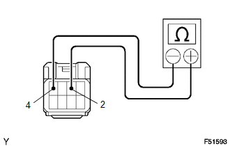
(a) Using an ohmmeter, check that there is resistance between terminals 2 and 4. Standard: 10 kΩ or higher If the result is not as specified, replace the clutch start cancel switch. |
|
|
(b) Connect the positive (+) lead from the battery to terminal 3 and connect negative (-) lead to terminal 1. |
|
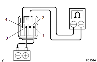
(c) Using an ohmmeter, check that there is resistance between terminals 2 and 4.
Standard:
10 kΩ or higher
If the result is not as specified, replace the clutch start cancel switch.
|
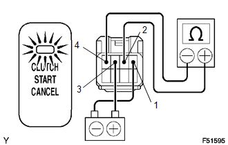
(d) Check that the indicator light comes on and there is resistance between terminals 2 and 4 when the switch is pressed. Standard: Below 1 Ω If the result is not as specified, replace the clutch start cancel switch. |
|
|
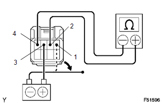
(e) Using an ohmmeter, check that there is resistance between terminals 2 and 4 when the battery lead is disconnected. Standard: 10 kΩ or higher If the result is not as specified, replace the clutch start cancel switch. |
|
 Clutch Release Cylinder(for Rc62f)
Components
COMPONENTS
ILLUSTRATION
Disassembly
DISASSEMBLY
PROCEDURE
1. REMOVE CLUTCH RELEASE CYLINDER KIT
(a) Remove the boot from the cylinder body.
(b) Remove the push rod from the bo ...
 Clutch System
...
Other materials:
Power Source Circuit
DESCRIPTION
This circuit provides power to operate the forward recognition camera.
WIRING DIAGRAM
CAUTION / NOTICE / HINT
NOTICE:
Inspect the fuses for circuits related to this system before performing the following
inspection procedure.
PROCEDURE
1.
CHECK HARNESS A ...
Diagnosis System
DIAGNOSIS SYSTEM
DIAGNOSIS FUNCTION
(a) The diagnosis function turns off the cruise control indicator, illuminates
the master warning light and displays a warning message when a malfunction is detected.
When a malfunction is detected in the dynamic radar cruise control system, DTCs
are store ...
Disassembly
DISASSEMBLY
PROCEDURE
1. REMOVE ROOM LIGHT BRACKET
(a) Disengage the guide to remove the room light bracket.
2. REMOVE SLIDING ROOF DRIVE GEAR SUB-ASSEMBLY
(a) Remove the 2 bolts and sliding roof drive gear sub-assembly.
...
