Toyota Tacoma (2015-2018) Service Manual: Central Gateway ECU Communication Stop Mode
DESCRIPTION
|
Detection Item |
Symptom |
Trouble Area |
|---|---|---|
|
Central Gateway ECU Communication Stop Mode |
Communication system DTCs (DTCs that start with U) that correspond to "Central Gateway ECU Communication Stop Mode" in "DTC Combination Table" are output. Click here |
|
WIRING DIAGRAM
CAUTION / NOTICE / HINT
CAUTION:
When performing the confirmation driving pattern, obey all speed limits and traffic laws.
NOTICE:
- Because the order of diagnosis is important to allow correct diagnosis,
make sure to begin troubleshooting using How to Proceed with Troubleshooting
when CAN communication system related DTCs are output.
Click here
.gif)
- Before measuring the resistance of the CAN bus, turn the ignition switch off and leave the vehicle for 1 minute or more without operating the key or any switches, or opening or closing the doors. After that, disconnect the cable from the negative (-) battery terminal and leave the vehicle for 1 minute or more before measuring the resistance.
- After turning the ignition switch off, waiting time may be required
before disconnecting the cable from the negative (-) battery terminal. Therefore,
make sure to read the disconnecting the cable from the negative (-) battery
terminal notices before proceeding with work.
Click here
- Some parts must be initialized and set when replacing or removing and
installing parts.
Click here
- After performing repairs, perform the DTC check procedure and confirm
that the DTCs are not output again.
DTC check procedure: Turn the ignition switch to ON and wait for 1 minute or more. Then operate the suspected malfunctioning system and drive the vehicle at 60 km/h (37 mph) or more for 5 minutes or more.
- After the repair, perform the CAN bus check and check that all the ECUs
and sensors connected to the CAN communication system are displayed as normal.
Click here
- Inspect the fuses for circuits related to this system before performing the following procedure.
HINT:
- Before disconnecting related connectors for inspection, push in on each connector body to check that the connector is not loose or disconnected.
- When a connector is disconnected, check that the terminals and connector body are not cracked, deformed or corroded.
PROCEDURE
|
1. |
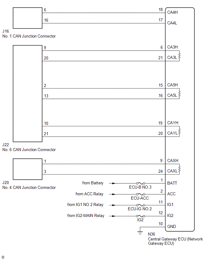
CHECK FOR OPEN IN CAN LINES (CENTRAL GATEWAY ECU (NETWORK GATEWAY ECU) CAN MAIN OR BRANCH LINE) |
|
(a) Disconnect the cable from the negative (-) battery terminal. |
|
(b) Disconnect the central gateway ECU (network gateway ECU) connector.
(c) Measure the resistance according to the value(s) in the table below.
Standard Resistance:
Bus 2|
Tester Connection |
Condition |
Specified Condition |
|---|---|---|
|
N36-18 (CA4H) - N36-17 (CA4L) |
Cable disconnected from negative (-) battery terminal |
54 to 69 Ω |
|
Tester Connection |
Condition |
Specified Condition |
|---|---|---|
|
N36-6 (CA3H) - N36-19 (CAYH) |
Cable disconnected from negative (-) battery terminal |
Below 1 Ω |
|
N36-21 (CA3L) - N36-20 (CAYL) |
Cable disconnected from negative (-) battery terminal |
Below 1 Ω |
|
Tester Connection |
Condition |
Specified Condition |
|---|---|---|
|
N36-15 (CA5H) - N36-9 (CAXH) |
Cable disconnected from negative (-) battery terminal |
Below 1 Ω |
|
N36-16 (CA5L) - N36-24 (CAXL) |
Cable disconnected from negative (-) battery terminal |
Below 1 Ω |
|
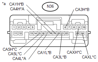
*A |
Bus 2 |
|
*B |
Bus 3 |
|
*C |
Bus 5 |
|
*a |
Front view of wire harness connector (to Central Gateway ECU (Network Gateway ECU)) |
|
Result |
Proceed to |
|---|---|
|
OK |
A |
|
NG (Bus 2 Branch Lines) |
B |
|
NG (Bus 3 or Bus 5 Main Lines) |
C |
| B | .gif) |
REPAIR OR REPLACE CAN BRANCH LINES OR CONNECTOR (CENTRAL GATEWAY ECU (NETWORK GATEWAY ECU)) |
| C | |
REPAIR OR REPLACE CAN MAIN BUS LINES OR CONNECTOR (CENTRAL GATEWAY ECU (NETWORK GATEWAY ECU)) |
|
.gif)
|
2. |
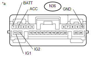
CHECK HARNESS AND CONNECTOR (POWER SOURCE CIRCUIT) |
|
(a) Measure the resistance according to the value(s) in the table below. Standard Resistance:
|
|
(b) Connect the cable to the negative (-) battery terminal.
(c) Measure the voltage according to the value(s) in the table below.
Standard Voltage:
|
Tester Connection |
Switch Condition |
Specified Condition |
|---|---|---|
|
N36-1 (BATT) - Body ground |
Always |
11 to 14 V |
|
N36-2 (ACC) - Body ground |
Ignition switch ACC |
11 to 14 V |
|
N36-11 (IG1) - Body ground |
Ignition switch IG |
11 to 14 V |
|
N36-12 (IG2) - Body ground |
Ignition switch IG |
11 to 14 V |
|
*a |
Front view of wire harness connector (to Central Gateway ECU (Network Gateway ECU)) |
| OK | |
REPLACE CENTRAL GATEWAY ECU (NETWORK GATEWAY ECU) |
| NG | |
REPAIR OR REPLACE HARNESS OR CONNECTOR |
 Radio Receiver Assembly Communication Stop Mode
DESCRIPTION
Detection Item
Symptom
Trouble Area
Radio Receiver Assembly Communication Stop Mode
Either condition is met:
Com ...
 Millimeter Wave Radar Sensor Communication Stop Mode
DESCRIPTION
Detection Item
Symptom
Trouble Area
Millimeter Wave Radar Sensor Communication Stop Mode
Either Condition is met:
...
Other materials:
Satellite Radio Broadcast cannot be Selected or After Selecting Broadcast, Broadcast
cannot be Added into Memory
CAUTION / NOTICE / HINT
NOTICE:
Some satellite radio broadcasts require payment. A contract must be made between
a satellite radio company and the user. If the contract expires, it will not be
possible to listen to the broadcast.
PROCEDURE
1.
CHECK NAVIGATION RECEIVER ...
Camper information
This information has been prepared in accordance with regulation issued by
the National Highway Traffic Safety Administration of the U.S. Department of Transportation.
It provides the purchasers and/or prospective purchasers of Toyota vehicles with
information on truck-camper loading. Your Toy ...
Rear Door(for Access Cab)
Adjustment
ADJUSTMENT
CAUTION / NOTICE / HINT
HINT:
Use the same procedures for both the LH and RH sides.
The procedure described below is for the LH side.
Centering bolts are used to mount the door hinge to the vehicle body
and door. The door cannot be adjusted with the ce ...
