Toyota Tacoma (2015-2018) Service Manual: CD Sound Skips
PROCEDURE
|
1. |
CHECK CD |
|
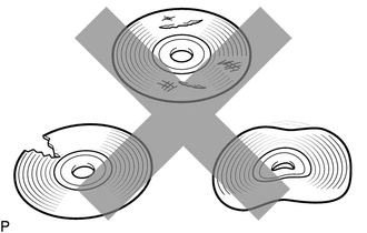
(a) Check that the CD is not deformed or cracked. OK: No deformation or cracks on the CD |
|
| NG | .gif) |
CD IS FAULTY |
|
.gif)
|
2. |
CHECK CD |
|
(a) Check the CD. OK: The CD is clean. NOTICE: Do not use a conventional record cleaner or anti-static preservative. HINT: If dirt is on the CD surface, wipe it clean with a soft cloth from the inside to the outside in a radial direction. |
|
.png)
| NG | |
CLEAN CD |
|
|
3. |
REPLACE CD AND RECHECK |
(a) Replace the CD with a known good one and check that the malfunction disappears.
OK:
Malfunction disappears.
| OK | |
CD WAS FAULTY |
|
|
4. |
CHECK RADIO AND DISPLAY RECEIVER ASSEMBLY |
(a) Check the radio and display receiver assembly installation condition.
(1) Check that the radio and display receiver assembly is properly installed.
OK:
The radio and display receiver assembly is properly installed.
| OK | |
REPLACE RADIO AND DISPLAY RECEIVER ASSEMBLY |
| NG | |
REINSTALL RADIO AND DISPLAY RECEIVER ASSEMBLY PROPERLY |
 CD cannot be Inserted / Played or CD is Ejected Right After Insertion
PROCEDURE
1.
CHECK IF A PROPER CD IS INSERTED
(a) Make sure that the CD is an audio CD or a CD with an MP3, WMA or AAC file,
and that it is not deformed, flawed, st ...
 Radio Broadcast cannot be Received or Poor Reception
PROCEDURE
1.
CHECK RADIO AND DISPLAY RECEIVER ASSEMBLY
(a) Check the radio automatic station search function.
(1) Check the radio automatic station search function b ...
Other materials:
Low Output Signal of Rear Speed Sensor RH (Test Mode DTC) (C1273,C1274,C1403,C1404)
DESCRIPTION
Refer to DTCs C1401 and C1402 (See page ).
DTC Code
DTC Detection Condition
Trouble Area
C1273
C1274
Stored only during test mode.
Rear speed sensor RH/LH
Rear speed sensor rotor RH/LH (rear ax ...
Blower Motor Circuit
DESCRIPTION
The blower motor with fan sub-assembly operates according to signals from the
air conditioning amplifier assembly. The blower motor with fan sub-assembly speed
signals are transmitted by changes in the duty ratio.
WIRING DIAGRAM
CAUTION / NOTICE / HINT
NOTICE:
Inspect the fuse ...
Dtc Check / Clear
DTC CHECK / CLEAR
NOTICE:
When the diagnosis system is changed from normal mode to check mode or vice versa,
all DTCs and freeze frame data recorded in normal mode are cleared. Before changing
modes, always check and make a note of DTCs and freeze frame data.
HINT:
DTCs which are sto ...
