Toyota Tacoma (2005–2015) Owners Manual: Auxiliary boxes
 Front
Front
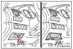
Pull the lid down.
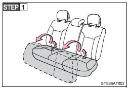
Under the rear seats (Access Cab
models)
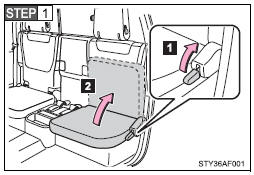
 Pull up the lever.
 Raise the bottom cushion up.
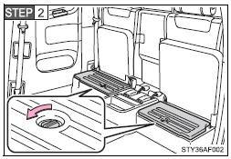
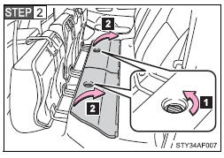
Turn the knob counterclockwise.
 Open the lid.
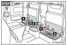
 Press the lid against the bottom
of the lower cushion until it is supported by the hookand- loop fastener.
Press the lid against the bottom
of the lower cushion until it is supported by the hookand- loop fastener.
Make sure that the lid is supported to prevent it from closing unexpectedly.
 Under the rear seats (Double Cab
models)
Under the rear seats (Double Cab
models)
Swing the bottom cushion up by pulling the lock release strap.
 Turn the knob counterclockwise.
 Open the lid.
CAUTION
■Caution while driving
Keep the auxiliary boxes closed and locked.
Injuries may result in the event of an accident or sudden braking.
 Bottle holders
Front
Front console box (Separated type
front seat)
Rear (Double Cab models)
■Bottle holders
Depending on their size or shape, some bottles may not fit in the holders.
NOTICE
` ...
 Overhead console (Access Cab and Double Cab models)
The overhead console is useful for temporarily storing sunglasses and similar
small items.
Pull the lid down while pushing the knob.
CAUTION
■Caution while driving
Keep the overhead cons ...
Other materials:
How To Proceed With Troubleshooting
CAUTION / NOTICE / HINT
HINT:
Use these procedures to troubleshoot the key reminder warning system.
*: Use the Techstream.
PROCEDURE
1.
VEHICLE BROUGHT TO WORKSHOP
NEXT
...
Yaw Rate Sensor Malfunction (C1436)
DESCRIPTION
The skid control ECU (brake actuator assembly) receives signals from the yaw
rate and acceleration sensor (airbag sensor assembly) via the CAN communication
system.
The airbag sensor assembly has a built-in yaw rate sensor and detects the vehicle
condition.
If there is trouble i ...
Adjustment
ADJUSTMENT
PROCEDURE
1. PREPARE VEHICLE FOR FOG LIGHT AIMING ADJUSTMENT
(a) Prepare the vehicle:
HINT:
Ensure that there is no damage or deformation to the body around the
fog lights.
Fill the fuel tank.
Make sure that the oil is filled to the specified level.
Make sure ...
