Toyota Tacoma (2015-2018) Service Manual: Wireless Door Lock Tuner Circuit Malfunction (B1242)
DESCRIPTION
The door control receiver is used to receive radio waves relating to the entry functions of the electrical key transmitter sub-assembly. The certification ECU (smart key ECU assembly) decodes the requested electrical key transmitter sub-assembly by identifying a key code based on the radio waves received via the door control receiver. The door control receiver receives a signal from the electrical key transmitter sub-assembly and sends signals to the main body ECU (multiplex network body ECU) through the certification ECU (smart key ECU assembly). The certification ECU (smart key ECU assembly) then sends a command, according to the requested operation, to each ECU (ex. if door lock operation is requested, the certification ECU (smart key ECU assembly) sends a door lock command to the main body ECU (multiplex network body ECU)).
|
DTC No. |
DTC Detecting Condition |
Trouble Area |
|---|---|---|
|
B1242 |
|
|
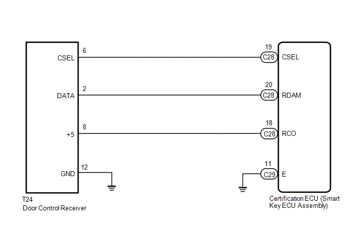
WIRING DIAGRAM
CAUTION / NOTICE / HINT
NOTICE:
- When replacing or inspecting the door control receiver and wire harness, do not change the position or length of the wire harness. If the wire harness is too close to the door control receiver, smart and wireless function performance may be affected.
- Before performing the inspection, check that there are no problems related
to the CAN communication system (See page
.gif) ).
).
- When replacing the door control receiver, read the transmitter IDs (tire
pressure warning system) stored in the old ECU using the Techstream and
write them down before removal (See page
).*
- It is necessary to perform registration (See page
) of the transmitter IDs into the door
control receiver if the door control receiver has been replaced.*
- This DTC is not detected within 10 seconds after the engine switch turned
to off from on (IG).
- *: w/ Tire Pressure Warning System
PROCEDURE
|
1. |
CHECK CERTIFICATION ECU (SMART KEY ECU ASSEMBLY) |
|
(a) Disconnect the door control receiver connector. |
|
(b) Measure the voltage and resistance according to the value(s) in the table below.
Standard Voltage:
|
Tester Connection |
Condition |
Specified Condition |
|---|---|---|
|
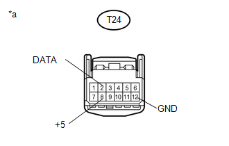
T24-8 (+5) - T24-12 (GND) |
Engine switch off, all doors closed and electrical key transmitter sub-assembly switch not pressed → electrical key transmitter sub-assembly switch pressed |
Below 1 V → 4.5 to 5.5 V (Pulse generation) |
|
T24-2 (DATA) - T24-12 (GND) |
Engine switch off |
11 to 14 V pulse generation at regular intervals |
Standard Resistance:
|
Tester Connection |
Condition |
Specified Condition |
|---|---|---|
|
T24-12 (GND) - Body ground |
Always |
Below 1 Ω |
|
*a |
Front view of wire harness connector (Door control receiver) |
| OK | .gif) |
REPLACE DOOR CONTROL RECEIVER |
|
.gif)
|
2. |
CHECK HARNESS AND CONNECTOR (DOOR CONTROL RECEIVER - CERTIFICATION ECU (SMART KEY ECU ASSEMBLY)) |
(a) Disconnect the certification ECU (smart key ECU assembly) connectors.
(b) Measure the resistance according to the value(s) in the table below.
Standard Resistance:
|
Tester Connection |
Condition |
Specified Condition |
|---|---|---|
|
C28-19 (CSEL) - T24-6 (CSEL) |
Always |
Below 1 Ω |
|
C28-20 (RDAM) - T24-2 (DATA) |
Always |
Below 1 Ω |
|
C28-18 (RCO) - T24-8 (+5) |
Always |
Below 1 Ω |
|
C29-11 (E) - Body ground |
Always |
Below 1 Ω |
|
T24-12 (GND) - Body ground |
Always |
Below 1 Ω |
|
C28-19 (CSEL) or T24-6 (CSEL) - Body ground |
Always |
10 kΩ or higher |
|
C28-22 (RDAM) or T24-2 (DATA) - Body ground |
Always |
10 kΩ or higher |
|
C28-18 (RCO) or T24-8 (+5) - Body ground |
Always |
10 kΩ or higher |
| OK | |
REPLACE CERTIFICATION ECU (SMART KEY ECU ASSEMBLY) |
| NG | |
REPAIR OR REPLACE HARNESS OR CONNECTOR |
 Diagnostic Trouble Code Chart
DIAGNOSTIC TROUBLE CODE CHART
HINT:
If a trouble code is output during the DTC check, inspect the trouble areas listed
for that code. For details of the code, refer to "See page" in the ...

Other materials:
Front Passenger Side Door ECU Communication Stop (B2322)
DESCRIPTION
This DTC is stored when LIN communication between the front power window regulator
motor assembly RH and main body ECU (multiplex network body ECU) stops for 10 seconds
or more.
DTC No.
DTC Detection Condition
Trouble Area
B2322
...
Components
COMPONENTS
ILLUSTRATION
ILLUSTRATION
ILLUSTRATION
ILLUSTRATION
ILLUSTRATION
ILLUSTRATION
ILLUSTRATION
...
Ambient Temperature Sensor Circuit (B1412)
DESCRIPTION
The ambient temperature sensor is installed in front of the condenser to detect
the ambient temperature which is used to control the air conditioning system AUTO
mode. This sensor is connected to the air conditioning amplifier assembly and detects
fluctuations in the ambient tempe ...
