Toyota Tacoma (2015-2018) Service Manual: ACC Signal Circuit
DESCRIPTION
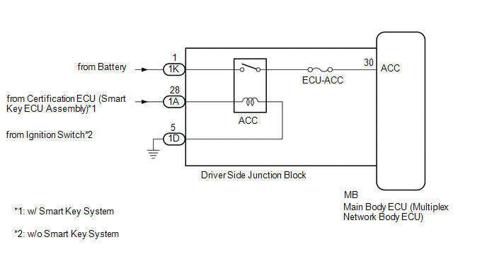
This circuit detects whether the ignition switch is ACC or off, and sends this information to the main body ECU (multiplex network body ECU).
WIRING DIAGRAM
CAUTION / NOTICE / HINT
NOTICE:
- Inspect the fuses for circuits related to this system before performing the following inspection procedure.
- If the main body ECU (multiplex network body ECU) is replaced, refer
to Registration (See page
.gif) ).*1
).*1
- *1: w/ Smart Key System
PROCEDURE
|
1. |
READ VALUE USING TECHSTREAM (ACC SW) |
(a) Connect the Techstream to the DLC3.
(b) Turn the ignition switch to ON.
(c) Turn the Techstream on.
(d) Enter the following menus: Body Electrical / Main Body / Data List.
(e) According to the display on the Techstream, read the Data List.
Main Body|
Tester Display |
Measurement Item/Range |
Normal Condition |
Diagnostic Note |
|---|---|---|---|
|
ACC SW |
Ignition switch ACC signal / ON or OFF |
ON: Ignition switch ACC OFF: Ignition switch off |
"ON" is also displayed for this item when the ignition switch is ON. |
OK:
The display is as specified in the normal condition column.
| OK | .gif) |
PROCEED TO NEXT SUSPECTED AREA SHOWN IN PROBLEM SYMPTOMS TABLE |
|
.gif)
|
2. |
CHECK HARNESS AND CONNECTOR (DRIVER SIDE JUNCTION BLOCK - BATTERY AND BODY GROUND) |
|
(a) Disconnect the driver side junction block connectors. |
|
(b) Measure the voltage according to the value(s) in the table below.
Standard Voltage:
|
Tester Connection |
Condition |
Specified Condition |
|---|---|---|
|
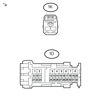
1K-1 - Body ground |
Always |
11 to 14 V |
(c) Measure the resistance according to the value(s) in the table below.
Standard Resistance:
|
Tester Connection |
Condition |
Specified Condition |
|---|---|---|
|
1D-5 - Body ground |
Always |
Below 1 Ω |
|
*a |
Front view of wire harness connector (to Driver Side Junction Block) |
| NG | |
REPAIR OR REPLACE HARNESS OR CONNECTOR |
|
|
3. |
CHECK HARNESS AND CONNECTOR (ACC POWER SOURCE CIRCUIT) |
|
(a) Disconnect the driver side junction block connector. |
|
(b) Measure the voltage according to the value(s) in the table below.
Standard Voltage:
|
Tester Connection |
Switch Condition |
Specified Condition |
|---|---|---|
|
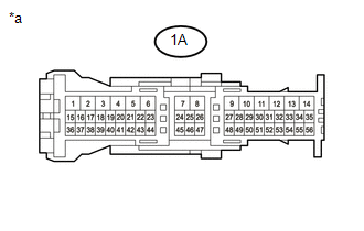
1A-28 - Body ground |
Ignition switch ACC |
11 to 14 V |
|
*a |
Front view of wire harness connector (to Driver Side Junction Block) |
| NG | |
REPAIR OR REPLACE HARNESS OR CONNECTOR |
|
|
4. |
CHECK DRIVER SIDE JUNCTION BLOCK |
|
(a) Remove the driver side junction block (See page
|
|
(b) Reconnect the 1K, 1A and 1D driver side junction block connectors.
(c) Measure the voltage according to the value(s) in the table below.
Standard Voltage:
|
Tester Connection |
Switch Condition |
Specified Condition |
|---|---|---|
|
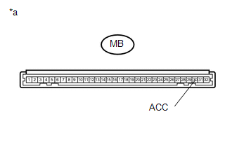
MB-30 (ACC) - Body ground |
Ignition switch ACC |
11 to 14 V |
|
*a |
Component without harness connected (Driver Side Junction Block) |
| OK | |
REPLACE MAIN BODY ECU (MULTIPLEX NETWORK BODY ECU) |
| NG | |
REPLACE DRIVER SIDE JUNCTION BLOCK |
 Turn Signal Switch Circuit
DESCRIPTION
The combination meter assembly receives the turn signal switch information and
controls the turn signal lights.
WIRING DIAGRAM
PROCEDURE
1.
READ VALUE USING ...
 Daytime Running Light Relay Circuit
DESCRIPTION
The main body ECU (multiplex network body ECU) controls the daytime running lights.
WIRING DIAGRAM
CAUTION / NOTICE / HINT
NOTICE:
Inspect the fuses for circuits related to ...
Other materials:
Propeller Shaft System
Problem Symptoms Table
PROBLEM SYMPTOMS TABLE
HINT:
Use the table below to help determine the cause of problem symptoms. If multiple
suspected areas are listed, the potential causes of the symptoms are listed in order
of probability in the "Suspected Area" column of the table. Che ...
Problem Symptoms Table
PROBLEM SYMPTOMS TABLE
HINT:
Use the table below to help determine the cause of problem symptoms.
If multiple suspected areas are listed, the potential causes of the symptoms
are listed in order of probability in the "Suspected Area" column of the
table. Check each sy ...
Transfer L4 Position Switch Circuit (C1268)
DESCRIPTION
A-TRAC is activated if wheel skid is detected while the transfer is in the L4
position.
DTC Code
DTC Detecting Condition
Trouble Areas
C1268
L4 detection switch signal input to skid control ECU (master cylinder
solenoid ...
