Toyota Tacoma (2015-2018) Service Manual: Front Upper Suspension Arm
Components
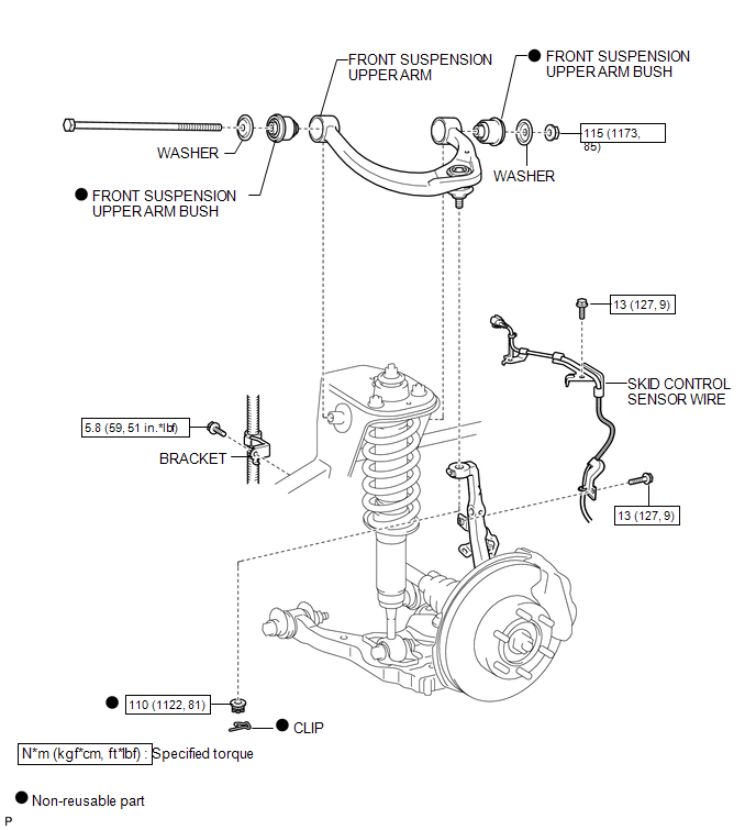
COMPONENTS
ILLUSTRATION
Disassembly
DISASSEMBLY
PROCEDURE
1. REMOVE FRONT SUSPENSION UPPER ARM BUSH
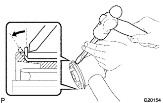
(a) Using a hammer and chisel, raise the flange of the bushing diagonally as shown in the illustration.
|
(b) Using SST and a press, remove the front suspension upper arm bush LH (front side). SST: 09613-26010 SST: 09710-22021 09710-01031 SST: 09950-00020 |
|
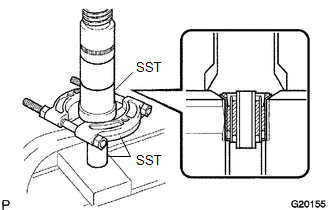
(c) The removal procedure for the rear side is the same as that for the front side.
Removal
REMOVAL
PROCEDURE
1. REMOVE FRONT WHEEL
2. INSPECT FRONT SUSPENSION UPPER ARM
(a) Check that there is no slack on the ball joint by shaking the upper arm up and down by hand.
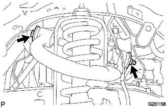
3. SEPARATE SKID CONTROL SENSOR WIRE
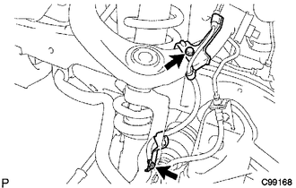
(a) Remove the 2 bolts, and separate the skid control sensor wire.
4. REMOVE FRONT SUSPENSION UPPER ARM
(a) Support the front suspension lower arm LH with a jack.
(b) Remove the clip and nut.
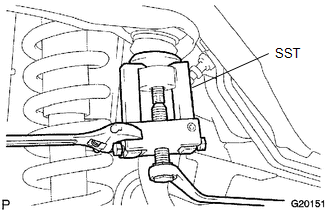
(c) Using SST, separate the upper ball joint from the steering knuckle.
SST: 09628-62011
|
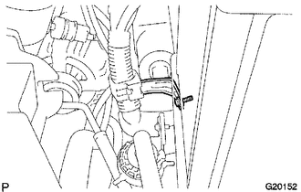
(d) Remove the bolt and bracket. |
|
|
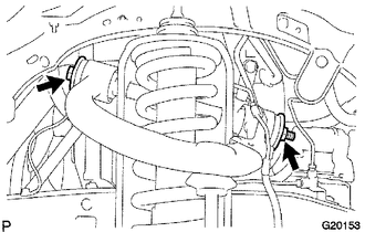
(e) Remove the bolt, 2 washers and nut. HINT: To prevent interference with the vehicle body when removing the bolt, raise the vehicle on a lift and set the suspension to full rebound. |
|
(f) Remove the front suspension upper arm.
Inspection
INSPECTION
PROCEDURE
1. INSPECT FRONT SUSPENSION UPPER ARM
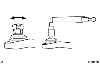
(a) Flip the ball joint stud back and forth 5 times, as shown in the illustration, before installing the nut.
(b) Using a torque wrench, turn the nut continuously at a rate of 3 to 5 seconds per turn and take the torque reading on the 5th turn.
Torque:
4.5 N·m {46 kgf·cm, 40 in·lbf}
or less
(c) Check for any cracks and grease leakage on the ball joint dust cover.
Installation
INSTALLATION
PROCEDURE
1. TEMPORARILY TIGHTEN FRONT SUSPENSION UPPER ARM
.png)
(a) Install the front suspension upper arm, and temporarily tighten the bolt, 2 washers and nut.
|
(b) Install the bracket with the bolt. Torque: 5.8 N·m {59 kgf·cm, 51 in·lbf} |
|
.png)
|
(c) Install a new nut and a new clip. Torque: 110 N·m {1122 kgf·cm, 81 ft·lbf} |
|
.png)
2. INSTALL SKID CONTROL SENSOR WIRE
.png)
(a) Install the skid control sensor wire with the 2 bolts.
Torque:
13 N·m {127 kgf·cm, 9 ft·lbf}
3. INSTALL FRONT WHEEL
Torque:
113 N·m {1152 kgf·cm, 83 ft·lbf}
4. STABILIZE SUSPENSION
(a) Lower the vehicle.
(b) Bounce the vehicle up and down several times to stabilize the suspension.
5. FULLY TIGHTEN FRONT SUSPENSION UPPER ARM
(a) Fully tighten the nut.
Torque:
115 N·m {1173 kgf·cm, 85 ft·lbf}
6. INSPECT AND ADJUST FRONT WHEEL ALIGNMENT
(See page .gif) )
)
Reassembly
REASSEMBLY
PROCEDURE
1. INSTALL FRONT SUSPENSION UPPER ARM BUSH
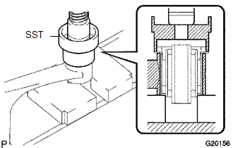
(a) Using SST and a press, install a new upper arm bush (front side).
SST: 09710-26010
09710-05061
(b) The installation procedure for the rear side is the same as that for the front side.
 Front Stabilizer Bar
Components
COMPONENTS
ILLUSTRATION
Inspection
INSPECTION
PROCEDURE
1. INSPECT FRONT STABILIZER LINK ASSEMBLY
(a) Flip the ball joint stud back and forth 5 times, as shown in the illustr ...

Other materials:
Reassembly
REASSEMBLY
CAUTION / NOTICE / HINT
HINT:
Use the same procedures for both the LH and RH sides.
The procedure described below is for the LH side.
PROCEDURE
1. INSTALL SIDE TURN SIGNAL LIGHT ASSEMBLY (w/ Side Turn Signal Light)
2. INSTALL OUTER MIRROR COVER (w/o Side Turn Si ...
Installation
INSTALLATION
CAUTION / NOTICE / HINT
CAUTION:
Be sure to perform this procedure with several people as the transfer assembly
is very heavy.
PROCEDURE
1. INSTALL TRANSFER CASE LOWER PROTECTOR
(a) Install the transfer case lower protector with the 4 bolts.
Torque:
18 N·m {184 kgf·cm, 13 f ...
Lost Communication with ECM (U0100,U0142,U0155)
DESCRIPTION
DTC No.
DTC Detecting Condition
Trouble Area
U0100
No communication with ECM
CAN communication system
ECM
U0142
No communication with main body ECU
...
