Toyota Tacoma (2015-2018) Service Manual: Certification Ecu
Components
COMPONENTS
ILLUSTRATION
Installation
INSTALLATION
PROCEDURE
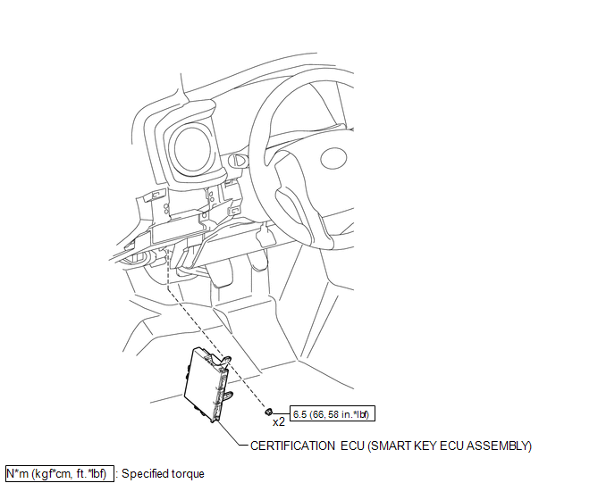
1. INSTALL CERTIFICATION ECU (SMART KEY ECU ASSEMBLY)
(a) Install the certification ECU (smart key ECU assembly) with the 2 nuts.
Torque:
6.5 N┬Ęm {66 kgf┬Ęcm, 58 in┬Ęlbf}
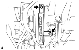
(b) Engage the clamp to install the wire harness.
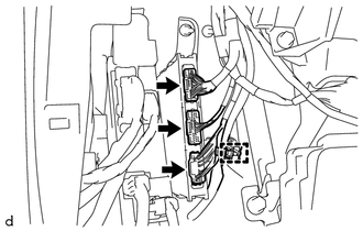
(c) Connect the 3 connectors.
2. INSTALL INSTRUMENT PANEL LOWER FINISH PANEL SUB-ASSEMBLY
(See page .gif) )
)
Removal
REMOVAL
PROCEDURE
1. REMOVE INSTRUMENT PANEL LOWER FINISH PANEL SUB-ASSEMBLY
(See page .gif) )
)
2. REMOVE CERTIFICATION ECU (SMART KEY ECU ASSEMBLY)
|
(a) Disconnect the 3 connectors. |
|
(b) Disengage the clamp to separate the wire harness.
|
(c) Remove the 2 nuts and certification ECU (smart key ECU assembly). |
|


Other materials:
Terminals Of Ecu
TERMINALS OF ECU
1. CHECK POWER WINDOW REGULATOR MASTER SWITCH ASSEMBLY
(a) for Double Cab
(1) Disconnect the P18 power window regulator master switch assembly connector.
(2) Measure the voltage and resistance according to the value(s) in the table
below.
HINT:
Measure the values on the wi ...
Installation
INSTALLATION
CAUTION / NOTICE / HINT
CAUTION:
Some of these service operations affect the SRS airbag system. Read the precautionary
notices concerning the SRS airbag system before servicing.
Click here
PROCEDURE
1. INSTALL FRONT SEAT INNER BELT ASSEMBLY
(a) for Driver Side:
(1) Install t ...
Disposal
DISPOSAL
PROCEDURE
1. DISPOSE OF FRONT SHOCK ABSORBER ASSEMBLY
(a) Fully extend the shock absorber piston rod, and fix it at an angle in a vise
or similar tool.
(b) Using a drill or similar tool, slowly make a hole in the shaded area shown
in the illustration, and discharge the gas inside. ...
