Toyota Tacoma (2015-2018) Service Manual: Vehicle Speed Signal Circuit between Radio Receiver and Combination Meter
DESCRIPTION
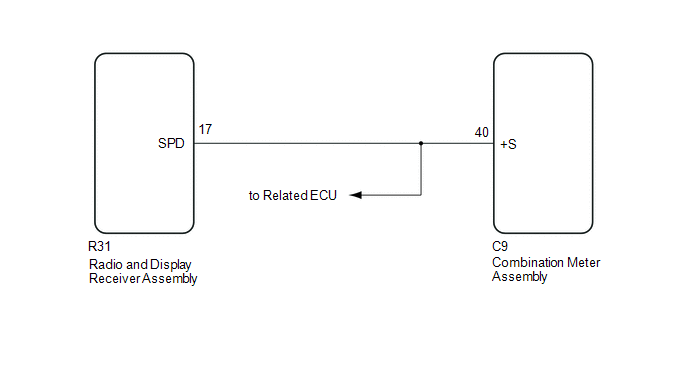
- The radio and display receiver assembly receives a vehicle speed signal from the combination meter assembly and sends the signal to radio and display receiver assembly.
- This circuit is necessary for the Automatic Sound Levelizer (ASL) built
into the radio and display receiver assembly.
The Automatic Sound Levelizer (ASL) function automatically adjusts the audio system volume level in order to compensate for increased vehicle noise (vehicle noise tends to increase as vehicle speed increases). The ASL adjusts the volume level based upon vehicle speed signals that it receives from the combination meter assembly.
- Vehicle speed signals are received from the combination meter assembly
and used to cancel "Bluetooth" function operation.
The radio and display receiver assembly recognizes that the vehicle is being to driven and makes it impossible to connect or register a "Bluetooth" device while driving.
HINT:
- A voltage of 12 V or 5 V is output from each ECU and then input to the combination meter assembly. The signal is changed to a pulse signal at the transistor in the combination meter assembly. Each ECU controls the respective system based on the pulse signal.
- If a short occurs in any of the ECUs or in the wire harness connected to an ECU, related components will not operate normally.
WIRING DIAGRAM
PROCEDURE
|
1. |
CHECK VEHICLE SIGNAL (OPERATION CHECK) |
|
(a) Enter the "Vehicle Signal Check Mode" screen. Refer to Check Vehicle
Signal Check Mode in Operation Check (See page
|
|
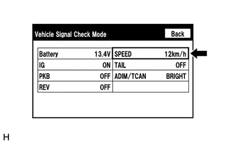
(b) While driving the vehicle, compare the "SPEED" indicator to the reading on the speedometer. Check if these readings are almost equal.
HINT:
The combination meter assembly receives the vehicle speed signal from the skid control ECU via CAN communication. Therefore, perform the following inspection referring to values on the Data List of the skid control ECU because it is the source of the vehicle speed signal.
OK:
Vehicle speed displayed on the "Vehicle Signal Check Mode" screen is almost the same as the actual vehicle speed measured using the Techstream.
- for Hydraulic Brake Booster Type (See page
.gif) )
) - for Vacuum Brake Booster Type (See page
)
| OK | .gif) |
PROCEED TO NEXT SUSPECTED AREA SHOWN IN PROBLEM SYMPTOMS TABLE |
|
.gif)
|
2. |
INSPECT COMBINATION METER ASSEMBLY (OUTPUT WAVEFORM) |
|
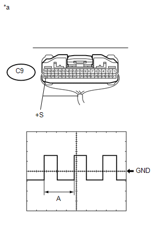
(a) Check the output waveform. (1) Remove the combination meter assembly with the connector still connected. (2) Connect an oscilloscope to terminal C9-40 (+S) and body ground. (3) Turn the ignition switch to ON. (4) Turn a wheel slowly. (5) Check the signal waveform according to the condition(s) in the table below.
OK: The waveform is similar to that shown in the illustration. HINT: When the system is functioning normally, one wheel revolution generates 4 pulses. As the vehicle speed increases, the width indicated by (A) in the illustration narrows. Text in Illustration
|
|
| NG | |
GO TO METER / GAUGE SYSTEM |
|
|
3. |
CHECK HARNESS AND CONNECTOR (RADIO AND DISPLAY RECEIVER ASSEMBLY - COMBINATION METER ASSEMBLY) |
(a) Disconnect the R31 radio and display receiver assembly connector.
(b) Disconnect the C9 combination meter assembly connector.
(c) Measure the resistance according to the value(s) in the table below.
Standard Resistance:
|
Tester Connection |
Condition |
Specified Condition |
|---|---|---|
|
R31-17 (SPD) - C9-40 (+S) |
Always |
Below 1 Ω |
| OK | |
REPLACE RADIO AND DISPLAY RECEIVER ASSEMBLY |
| NG | |
REPAIR OR REPLACE HARNESS OR CONNECTOR |
 Black Screen
PROCEDURE
1.
CHECK DISPLAY SETTING
(a) Check that the display is not in "Screen Off" mode.
OK:
The display setting is not in "Screen Off" mode. ...
 Steering Pad Switch Circuit
DESCRIPTION
This circuit sends an operation signal from the steering pad switch assembly
to the radio and display receiver assembly.
If there is an open in the circuit, the audio system cannot be ...
Other materials:
A/C ECU Vehicle Information Reading/Writing Processor Malfunction (B15F5)
DESCRIPTION
This DTC is stored when items controlled by the Air conditioning amplifier assembly
cannot be customized via the navigation system vehicle customization screen.
HINT:
The Air conditioning amplifier assembly controls the air conditioning system
related items that are customizable v ...
Removal
REMOVAL
PROCEDURE
1. REMOVE ROOF HEADLINING ASSEMBLY (for LED Type Stop Light)
for Double Cab:
(See page
)
for Access Cab:
(See page
)
2. REMOVE CENTER STOP LIGHT ASSEMBLY (for Bulb Type Stop Light)
(a) Apply protective tape around the center stop light as ...
Diagnostic Trouble Code Chart
DIAGNOSTIC TROUBLE CODE CHART
Dynamic Radar Cruise Control System
DTC No.
Detection Item
Link
C1A02
Vehicle Information Not Obtained
C1A0A
Front Radar Sensor Region Code Mismatch
...
