TERMINALS OF ECU
1. CHECK MAIN BODY ECU (MULTIPLEX NETWORK BODY ECU) AND DRIVER SIDE JUNCTION BLOCK
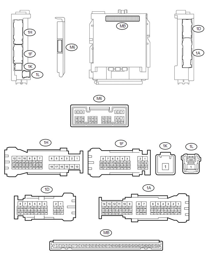
(a) Remove the main body ECU (multiplex network body ECU) from the driver side
junction block (See page .gif) ).
).
(b) Disconnect the 1D driver side junction block connector.
(c) Measure the voltage and resistance according to the value(s) in the table below.
|
Terminal No. (Symbol) |
Wiring Color |
Terminal Description |
Condition |
Specified Condition |
|---|---|---|---|---|
|
MB-11 (GND1) - Body ground |
None - Body ground |
Ground |
Always |
Below 1 Ω |
|
MB-31 (BECU) - Body ground |
None - Body ground |
Battery power supply |
Always |
11 to 14 V |
|
MB-30 (ACC) - Body ground |
None - Body ground |
ACC power supply |
Ignition switch ON(ACC) |
11 to 14 V |
|
MB-32 (IG) - Body ground |
None - Body ground |
Ignition switch power supply |
Ignition switch ON(IG) |
11 to 14 V |
|
1D-31 (KSW) - Body ground |
G - Body ground |
Unlock warning switch input |
No Key in ignition key cylinder (off) |
10 kΩ or higher |
|
Key inserted ignition key cylinder (on) |
Below 1 Ω |
(d) Install the main body ECU (multiplex network body ECU) to the driver side
junction block (See page ).
(e) Reconnect the 1D driver side junction block connector.
(f) Measure the voltage and check for pulse according to the value(s) in the table below.
|
Terminal No. (Symbol) |
Wiring Color |
Terminal Description |
Condition |
Specified Condition |
|---|---|---|---|---|
|
M6-6 (FLCY) - Body ground |
Y - Body ground |
Front door LH courtesy light switch input |
Front door LH open |
Below 1 V |
|
Front door LH closed |
Pulse generation |
|||
|
1D-31 (KSW) - Body ground |
G - Body ground |
Unlock warning switch input |
No Key in ignition key cylinder (off) |
11 to 14 V |
|
Key inserted ignition key cylinder (on) |
Below 1 V |